- DIY Robotic Articulated Hand
- How it all started?
- Things required for making articulated hand
- Steps for Making Robotic Articulated Hand
- Step #1: Tracing and Cutting
- Step # 2: Bending the cardboard to make fingers
- Step #3: Straw cutting and pasting
- Step #4: Pass the twine and tie beads
- Step #6: Make a handle
- 3D Printed Articulated Finger Extensions
- Introduction: 3D Printed Articulated Finger Extensions
- Supplies
- Step 1: Why I Made This
- Step 2: How It Moves
- Step 3: Design Choices
- Orientation of all parts
- Wire hinge
- Gearing mechanism
- Step 4: Determining the Size
- Step 5: 3D Printing the Parts
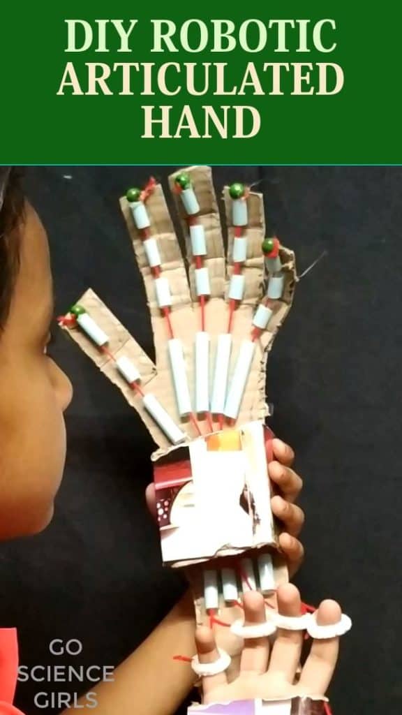
DIY Robotic Articulated Hand
Let’s make an articulated robotic hand that can be controlled with kid’s finger movements.

This is an activity that will describe the finger movements to kids with an easy explanation. You can also try this at home with kids. We have uploaded step by step demonstration for your easy reference.
How it all started?
My younger kid is very naughty and once she playfully closed the door when my elder one was keeping her hands in the closure. Her fingers got caught and she had pain. It was not very harsh though so I managed to keep ice cubes to relieve her from pain. At that time she was asking me about how the finger bends and why thumb finger has only two partitions while others have 3 etc. To cut the story short, these questions inspired me to teach her the anatomy of fingers with a DIY experiment.
Things required for making articulated hand
Before we talk about science, let us first see how to make this articulated hand model using simple things available at home. We bought few things from our local store. But, we have provided some links for your reference which you can refer to order online.
- Cardboard – To trace and make the hand base
- Beads – For decorating at the fingertips
- Pen – Trace the hand and fingers
- Scissors – For cutting
- Sticky tapes – To hold the joints, etc
- Straws preferably paper straw – To allow the twine to pass through and imagine straws as bones
- Yarn or twine – These allows fingers to bend and will act as tendons
- Glue gun – For pasting purposes
- Ruler – To make bends at the joints of the finger
[*Product links are affiliate links. Your support is highly appreciated]
Steps for Making Robotic Articulated Hand
Step #1: Tracing and Cutting
Trace the hand on the cardboard by placing the hands on it in such a way that the fingers are facing you. Cut the outline and refer video to know how much tracing is required.
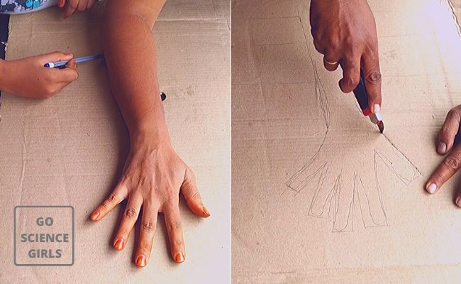
Step # 2: Bending the cardboard to make fingers
Use a ruler and bend places on the finger-like we bend our fingers. There are three lines in each finger and bending is complete in the portion where the fingers and the palm are connected. The next line also fingers bend thoroughly except for thumb finger. The topmost line in the finger bends partially. Make sure you check this action so give a perfect movement to your articulated fingers.
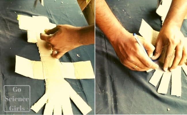
Step #3: Straw cutting and pasting
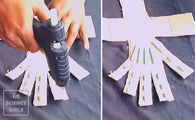
Cut the paper straw into small pieces to make fingers with bones as well as tendons. Cut them small and place them in between each bend you just made. Remember the twine will pass through this straw and make the movement of the fingers possible. So place straw pieces in equal distance.
The straw will act as bones for fingers and twine as the tendons.
Note: You must make sure to give a gap between each straw and that is the best way to let the fingers bend flexibly. Also, do not tighten too much which will make it rigid and the hand anatomy will not be reflected properly.
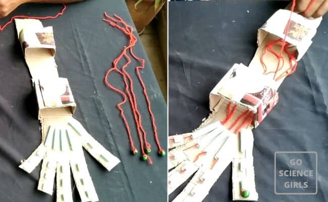
Step #4: Pass the twine and tie beads
Cut strings into pieces and for length refer to the video. Tie the beads to the string pieces and 5 beads are required for one finger. Connect them with the straw to the thumb and other fingers too. However, beads are optional. You can skip beads and pass through twine in the straw as we did as well.
Ensure twine length and give enough space to allow it to move.
Step #6: Make a handle
Holding will become simple with the help of this cardboard cutting. Fold them and use glue gun to fix the handle. You must cut it that way and fix your hands inside.
Finally we used pipe cleaners to create rings for each finger and attached them to the twines. You can use actual play rings if you have.
It is over and the hands are ready to make any movement. You can hold things, play with the gun and much more.
Paste straws with the glue gun and allow it to try so that it is fixed correctly.
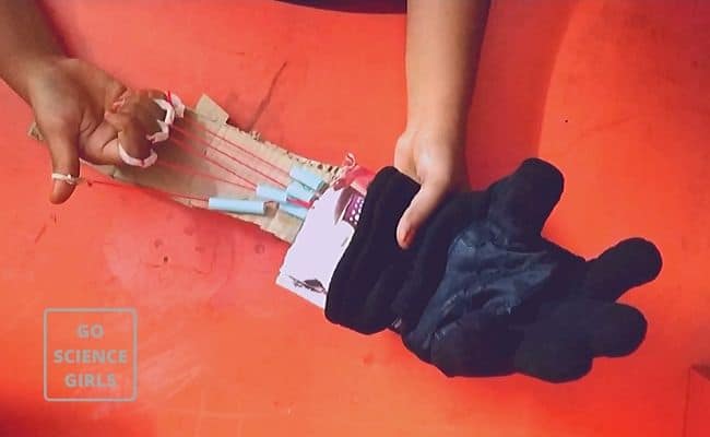
I let the girls have fun for some time. Then we are ready for our final bit.. now that we made bones, tendons and nerves, why not we add flesh to make it look like a real hand.
My elder daughter suggested we should try inserting this hand in a glove to see whether it looked like a real hand.. Here is how we tried it..
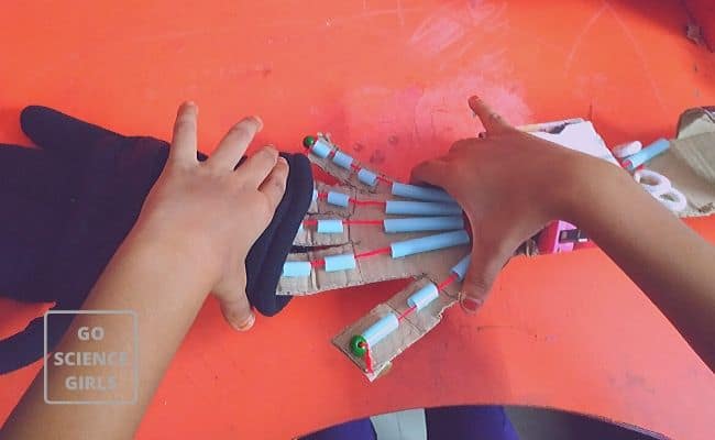
Since we used cardboard, it was bit difficult to get it inside the glove. But we finally succeeded with few extra folds in the cardboard. That made the hand more flexible and less sturdy. But we could still use it to make finger movements.
- Every finger has three bones whereas thumb has only 2. We call these bones as phalanges. That is why there are two lines in the thumb and three for other fingers to separate each small bone. We have straws to show them externally.
- These phalanges will connect to the five bones present in the main portion of the hand. That is named as metacarpals. (You can find 8 bones in the wrist which are called carpals, but we have not shown that in our handcraft.)
- The forearm contains the muscle which actually moves the thumb and the fingers.
- Long flexor tendons are the one that extends from the forearm muscle and passes through the wrist as well as the palm to the thumb and fingers.
- Tendon sheath is the place where the tendon slide and this passes through a snug tunnel. This is attached to the small bones of the thumb and other fingers. The tendons are held in place with the help of these sheaths. Contraction of forearm muscles will pull the tendons and thus the bones are moved.
Since the tendons are linked to the fingertip from the forearm, whenever there is minor damage in tendon it will affect the entire finger. I explained this to my kid and hence she suffered pain when the door slashed on her fingers.
The hand contains the veins and the arteries where the blood flows from and to the fingertips. The nerves present will let the feelings happen when you touch something with the fingers and hands. Indeed hands make a vital part of our body. These nerves are represented by the twine that forms the fibrous tendons.
It is a tricky activity but aptly suits 5+ years kids. We must provide help to them to make it work properly. However, 7+ kids can do it on their own.
For kids above age 8 can understand the anatomy and so teach in detail about the finger science.
Try this DIY and share your feedback for improvement. Trust the video helps you make a hand model at ease. Refer this link for better understanding in case you wish to go in-depth about hand science to kids.
Источник
3D Printed Articulated Finger Extensions

Introduction: 3D Printed Articulated Finger Extensions


Creepy and intricate, I have always loved seeing the articulated finger extensions. Recently I decided that I wanted a set of my own to match a previous project. Not content with what was already out there, I decided to make my own design.
The project shared here is my current prototype. It does not yet meet all my requirements in regards to looks, but it is already fully functional and can be made by anyone interested.
Supplies
Tools:
- A 3D printer
- A craft knife
- A lighter
- A drill
- A 1mm drill
- A 1.75mm or 1.8mm drill
- If a drill is not possible, a piece if iron wire of 1,5-1.8mm will also work. See «Preparing» step
- (Calipers)
materials (optional in parenthesis):
- Filament (preferably 1,75mm)
- Fishing line or thin strong wire
- CA glue
- (Activator for CA glue)
- (Elastic wire or rubber bands)
- (Zipties)
- (Something that straps around your wrist)
Step 1: Why I Made This
Why did I make this? First of all, because I can and they are awesome.
My first encounter with the articulated finger mechanism was when I saw them on Tested (video) where Adam Savage showcased them. As is often the case, I vaguely remember it, and rediscover it later with more passion.
A few weeks ago was when I got that passion. I wanted to make a set. Preferably one that matched the 3D printed scales I already have (link to scales). I started looking around the internet to find existing plans. Why design something that already exists. Gary Fey, the creator of the vingers in the first video only sells the fingers themselves. There were 2 reasonable options.
The first option was on thingiverse. These finger extensions were more closely resembling the model by Gary Fey, using a pulling system on the top of the finger (more in the next step). It is designed to be as compact as possible, and the be reskinned with another file. It is brilliantly compact, seems to work well, and should be a decent print. It was also one I did not try myself, because I found something else first.
The second is a model you have to pay for on Cults3d. It is a design that has the style in the part itself. In my case, robot, but there is also dragon and skeleton. It is a pusher system which is a bit limiting in the movement, and places push bars on the inside of the hand. My finger can only move by 45 degrees for the full movement of the extension. I printed a single finger. While it was somewhat optimized for 3D printing, it was a supported print. It also tended to bind a bit because of how the linkages are placed. The style did not really match with anything I wanted, but that is not a valid complaint. There was no real information on the dimensions, so I had to print a random size and hope. It worked fairly okay, but I would have wanted better measurements to determine what I needed to print.
After printing the single finger I wanted to try designing it myself. I wanted a few things.
- Make the design easily modifiable so I can alter it to my hands (and anyone else’s if I do it right)
- Make the extension’s movement happen in as close as 90 degrees of finger movement as possible.
- Make the design move smoothly. This basically requires the Gary Fey puller design.
- Make it supportless. I hate supports on mechanical parts, and felt it would be possible to make a design without supports.
- Make the design match my scales (not in this Ible)
This Instructable is my first prototype of supportless articulated finger extensions.
Step 2: How It Moves
The basic idea of the finger extensions is that it takes the movement of your finger, and extends it to several more joints. The movement of the first 2 sections (from the right) are used to move the next 2 sections of finger.
On the first joint there is a linkage that is attached to the leftmost section of the finger. This linkage goes into a gear set that inverts the movement so it goes the right way. A linkage is used to convey the movement from the middle of the mechanism to the tip of the mechanism.
I have included images and a gif to hopefully give a good overview of how it works.
Step 3: Design Choices
There are a few design choices that I do want to share with the people making this mechanism. These will hopefully help people understand some of the choices I made, and maybe aid people trying to design this themselves.
Orientation of all parts
One of the main reasons to make my own design is to try and make it support free. This means that all parts cannot have overhangs greater than roughly 45 degrees, and only short bridges. Given that all fingers have some sort of linkage running through them, this kind of forces me to print all finger related parts upright. Printing them on the side would give difficult bridges to print. The ring at the base of the finger also needs to accommodate the almost 90 degree motion of the finger itself, forcing it to have a 45 degree angle. The same goes for all other finger joints, which need to move past each other. In order to keep the design itself calm, I wanted all finger joints printed in the same orientation. I went with 55 degrees. This makes it simpler to print due to limited overhang, and gives all joints room to move 90 degrees. All gears and linkages are printed flat on the bed. The joint right after the gears was split up into 3 pieces in order to make it printable.
Wire hinge
The first hinge around the finger is the most challenging part of the design. While most hinges on the extensions have width available to them, around the finger there is a finger in the way. There are also up to two fingers, one on each side, sitting very close to the hinge. This forces the hinge to be fairly narrow. I first tried making the hinge as a conventional hinge (as seen in the photo). This hinge was still quite large, fragile, and difficult to print.
Gary Fey seems to have encountered this problem as well, and made some sort of living hinge. While technical details are not shared (he sells them after all) it is clear that he uses some type of living (or bending) hinge. I suspect he uses a coil spring, potentially with a cable running through it as a hinge. While I would be able to design this and make this, it would make replicating this project problematic.
I opted to use a bit of a hybrid. The first joint consists of a sort of ball and socket design. A flexible wire pulls the joint together. The part around the base of the finger has clearance for the wire to move when the finger bends. The fingertip has a smooth channel and the «ball» that runs in the socket. The channel runs at an angle of 45 degrees so that there is 45 degrees of movement to either side. On either side there is some length to the cable before it is mounted to give the cable some room to flex. This design functions because the finger itself has a functional joint. All the wire hinge does is keep the parts together. This hinge is narrower and strong enough to work. The only downside is that it adds some sort of flexible wire such as fishing wire to the bill of material.
Gearing mechanism
The finger extensions take the movement of the finger, and extend it to several more joints. Getting this movement from the finger to the first joint is the biggest challenge. Some sort of linkage is used to convey the movement. The linkage needs from one side of your hand to the other in order to pull the finger in the right direction. This crossing is easy through the mechanism, but around the finger itself it is difficult, since there is a finger there. If the linkage moves 1cm, there needs to be a 1cm gap after the fingertip for the linkage to move.
Gear mechanism that Gary Fey uses solves part of this problem. It makes it so that the linkage has both joints on the top of the finger. The gear inverts the movement before passing it to the next joint. This gearing takes space as well, but the linkage can be more compact and generally takes less space the passing the linkage to the other side of the hand.
Step 4: Determining the Size
To get the right size of finger, you will need to measure your hand. The easiest way is to use a calipers to measure the indicated spots of the finger. You measure by placing the calipers over the indicated spot and have it barely touching. Make sure you do not squeeze the finger. This will make you measure too small a value. All dimensions are in millimeters.
- For the thicknesses you want the thickest parts at the indicated points, usually plus 1mm to have some clearance.
- For the width you measure the width of the widest part, plus around 1mm. You need to exclude the webbing of your finger, the part moves around your webbing.
- For the length you measure the distance between the middle of the wrinkles of your fingers and the very end of the tip of the finger. Here you add at least 2mm, because a finger becomes longer when it bends.
Adding 1mm to width and thickness is important. This design binds easily to the finger, making it difficult to remove from a finger. My first prototype almost needed to be cut open to remove it, even though it fit perfectly.
The dimensions you need for a single finger are:
- «Base thickness»: The thickness of the base of the finger
- «Base Width»: The width of the base of the finger
- «Base length»: The length to the first joint + around 2mm
- «Joint thickness»: The thickness of the first joint
- «Joint width»: The width of the first joint
- «tip thickness»: The thickness of the tip (around the nail)
- «Tip width»: The width of the tip (around the base of the nail)
- «Tip length»: The length from the first joint to the tip + around 2mm
Since each finger is based on the same file, the dimensions will be included in the filename. All given dimensions are in millimeters in the filename, in the order of the list above, so the filename will be constructed:
My index finger for instance is: AFE-Finger-T22-W21-L31-T21-W21-T15-W17-L55
What sizes are available
Finger:
Thumb:
Given that I have no good database of hand dimension, and only have my own thin long hands as reference, I have made a guesstimate of some sizes that might be useful. If a size close enough is not on the list, for the first while after this project I will be creating new files on demand. Give the list of dimensions that you need and I will make it. Do however look if there is not already a file which matches yours fairly closely (1-2mm too big fits just fine) since I do not plan to make creating new hand files my full time hobby. Also do give me a few days to make the files, I do also lead a life.
(Be aware that since most models are automatically generated, they may have mistakes. I try to catch most of them, but I cannot guarantee that all files work perfectly. If you encounter a file that works poorly let me know and I will fix it)
Step 5: 3D Printing the Parts
As mentioned before, all parts are supportless. Any printer capable of overhangs of 45 degrees should be able to print the parts for a finger. I printed mine on a Prusa Mk2s. A single finger takes around 4 hours to print at 0.2mm layer height and takes around 30-40g of filament (10-12m). A thumb prints faster at 2,5 hours.
Lower layer heights should give you a better printing experience at the angles of the parts. This will increase the print time however. Also, some parts have only a small amount of surface stuck to the printbed. I myself print on gluestick, even though I have a PEI bed. I do not know how these parts print if you have poor bed adhesion.
It is important to keep all parts of a file together after printing. There are no identifications on the parts, and size differences can be small. I keep all parts in separate bins after printing and assemble one finger at a time.
Getting the files
For now I have included the files with this instructable. I will probably find another place to stash them if I get more sizes, but they will remain available for free.
Источник