Спутниковое телевидение
- MIGSAT.RU »
- Ремонт »
- Схема тестера на Arduino Pro Mini с цветным дисплеем
Схема тестера на Arduino Pro Mini с цветным дисплеем
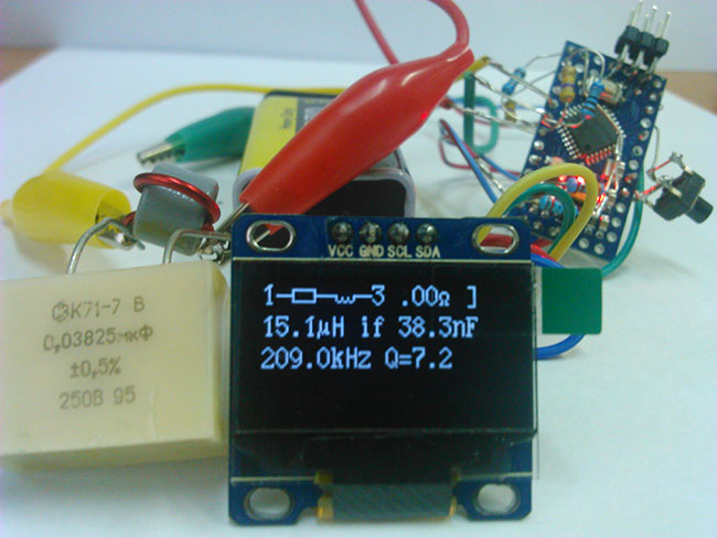
Недавно я нашел на просторах интернета краткое описание и схему о том, как самому в домашних условиях собрать тестер полупроводниковых элементов на микроконтроллере Atmega328P. ESR тестер на построен на плате Arduino Pro Mini плюс имеет дисплей TFT 1.8″ 128*60 SPI Color TFT L на базе контроллера ST7735. Эти модули можно купить AliExpress по доступной цене.
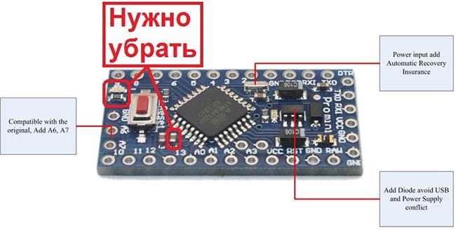
Необходима доработка платы Arduino Pro Mini:
Начал изучать схему Arduino Pro Mini и выяснил, что все вывода от микроконтроллера Atmega328P на самой плате как и полагается правильно разведены. Более того в плату запаян стабилизатор 5 вольт. Единственно необходимо выпаять на плате Arduino Pro Mini с микроконтроллером Atmega328P — несколько деталей.
— Убрать конденсатор 0,1мкФ с вывода AREF и выпаять резистор и светодиод от вывода (PB5 (SCK/PCINT5))
 Что касется кварца, то в Arduino Pro Mini уже установлен кварц на 16 МГц. Его оставляем.
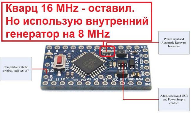
Схема тестера на Arduino Pro Mini с цветным дисплеем
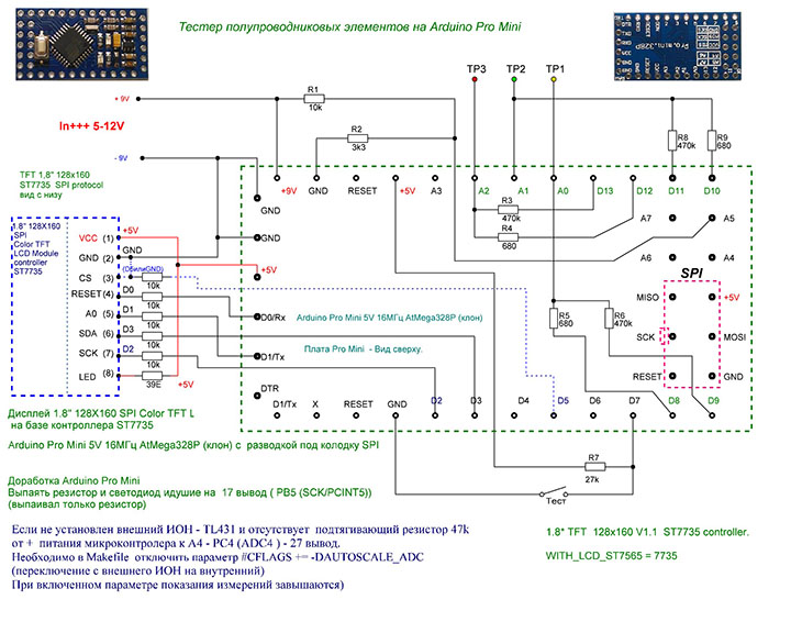
Список электронных компонентов для сборки ESR тестера
Резистор 680 Ом — 3 шт.
Резистор 3,3 кОм — 1 шт.
Резистор 10 кОм — 6 шт.
Резистор 27 кОм — 1 шт.
Резистор 470 кОм — 3 шт.
Резистор 39 Ом — 1 шт.
Кнопка обычная — 1 шт.
Плата Arduino Pro Mini — 1 шт.- стоимость в Китае 100-120 руб.
Дисплей TFT 1.8″ 128*60 SPI Color TFT L на базе контроллера ST7735 — стоимость в Китае 150-200 руб.
Для прошивки arduino mini использовал следующий программатор. Как подключить программатор USBASP смотрите схему ниже. Заказывал в Китае на AliExpress.
Источник
Arduino CAP-ESR-FREQ Meter © GPL3+
A metering instrument to measure capacitance, ESR value and frequency.
| × | 1 |
CAP-ESR-FREQ meter with an Arduino Duemilanove.
In this tutorial you can find all neccessary information about a metering instrument based on an Arduino Duemilanove. With this instrument you can measure three things: capacitor values in nanofarads and microfarads, the equivalent serie resistance (ESR value) of a capacitor and last but not least frequencies between 1 Herz an 3 MegaHerz. All three designs are based upon descriptions I found on the Arduino forum and on Hackerstore. After adding some updates I combined them into one instrument, controlled with just one Arduino ino program. The different meters are selected via a three position selector switch S2, connected to pins A1, A2 and A3. ESR zeroing and meter selection reset is done via a single pushbutton S3 on A4. Switch S1 is the power ON/OFF switch, needed for 9 V DC battery power when the meter is not connected to a PC via USB.These pins are used for input:A0: esr value input.A5: capacitor input.D5: frequency input.
The meter uses a Liquid Crystal Display (LCD) based on the Hitachi HD44780 (or a compatible) chipset, which is found on most text-based LCDs. The library works in 4- bit mode (i.e. using 4 data lines in addition to the rs, enable, and rw control lines). I started this project with an lcd with only 2 datalines the (SDA and SCL I2C connections) but unfortunally this conflicted with the other software I used for the meters. First I will explain he three different meters and finally the assembly instructions. With each type of meter you can also download the separate Arduino ino file, if you want to only install that specific type of meter.
Step 1: The Capacitor Meter
The digital capacitor meter is based on a design from Hackerstore. Measuring the value of a capacitor:
Capacitance is a measure of the ability of a capacitor to store electrical charge. The Arduino meter relies on the same basic property of capacitors: the time constant. This time constant is defined as the time it takes for the voltage across the capacitor to reach 63.2% of its voltage when fully charged. An Arduino can measure capacitance because the time a capacitor takes to charge is directly related to its capacitance by the equation TC = R x C. TC is the time constant of the capacitor (in seconds). R is the resistance of the circuit (in Ohms). C is the capacitance of the capacitor (in Farads). The formula to get the capacitance value in Farads is C = TC/R.
In this meter the R value can be set for calibration between 15kOhm and 25 kOhm via potmeter P1. The capacitor is charged via pin D12 and discharged for a next metering via pin D7. The charged voltage value is measured via pin A5. The full analog value on this pin is 1023, so 63.2% is represented by a value of 647. When this value is reached, the program calculates the capacitor value based on the above mentioned formula.
Step 2: The ESR Meter
See for the original Arduino forum topic https://forum.arduino.cc/index.php?topic=80357.0 Thanks to szmeu for the start of this topic and mikanb for his esr50_AutoRange design. I used this design including most of the comments and improvements for my esr meter design.
Equivalent Series Resistance (ESR) is the internal resistance that appears in series with the device’s capacitance. It can be used to find faulty capacitors during repair sessions. No capacitor is perfect and the ESR comes from the resistance of the leads, the aluminium foil and the electrolyte. It is often an important parameter in power supply design where the ESR of an output capacitor can affect the stability of the regulator (ie, causing it to oscillate or over react to transients in the load). It is one of the non-ideal characteristics of a capacitor which may cause a variety of performance issues in electronic circuits. A high ESR value degrades the performance due to power losses, noise, and a higher voltage drop.
During the test, a known current is passed through the capacitor for a very short time so the capacitor doesn’t charge completely. The current produces a voltage across the capacitor. This voltage will be the product of the current and the ESR of the capacitor plus a negligible voltage due to the small charge in the capacitor. Since the current is known, the ESR value is calculated by dividing the measured voltage by the current. The results are then displayed on the meter display. The test currents are generated via transistors Q1 and Q2, their values are 5mA (high range setting) and 50mA, (low range setting) via R4 and R6. Discharching is done via transistor Q3. The capacitor voltage is measured via analog input A0.
Step 3: The Frequency Meter
See for the original data the Arduino forum: https://forum.arduino.cc/index.php?topic=324796.0#main_content_section .Thanks to arduinoaleman for his great frequency meter design.
The frequency counter works as follows: The 16bit Timer/Counter1 will add up all clocks coming in from pin D5. Timer/Counter2 will generate an interrupt every millisecond (1000 times per second). If there is an overflow in Timer/Counter1, the overflow_counter will be increased by one. After 1000 interrupts (= exactly one second) the number of overflows will be multiplied by 65536 (this is when the counter flows over). In cycle 1000 the current value of the counter will be added, giving you the total number of clock ticks that came in during the last second. And this is equivalent of the frequency you wanted to measure (frequency = clocks per second). The procedure measurement(1000) will set up the counters and initialise them. After that a WHILE loop will wait until the interrupt servive routine sets measurement_ready to TRUE. This is exactly after 1 second (1000ms or 1000 interrupts). For hobbyists this frequency counter works very well (apart from lower frequencies you can get 4 or 5 digit accuracy). Especially with higher frequencies the counter gets very acurate. I have decided to display only 4 digits. However, you can adjust that in the LCD output section. You must use D5 pin of the Arduino as the frequency input. This is a prerequirement for using the 16bit Timer/Counter1 of the ATmega chip. (please check the Arduino pin for other boards). To measure analog signals or low-voltage signals a preamplifier is added with a pre-amplifier transistor BC547 and a block pulse shaper (Schmitt trigger) with a 74HC14N IC.
Step 4: The Components Assembly
The ESR and CAP circuits are mounted on a piece of perfboard with holes 0.1 inch distance. The FREQ circuit is mounted on a separate perfboard (this circuit was added later). For the wired connections male headers are used. The lcd screen is mounted in the top cover of the box, together with the ON/OFF switch. (And one spare switch for future updates). The layout was made on paper (much easier than using Fritzing or other design programs). This paper layout was later also used to check the real circuit.
Step 5: The Box Assembly
A black plastic box (dimensions WxDxH 120x120x60 mm) was used to mount all components and both circuit boards. The Arduino, the perfboard circuits and the battery holder are mounted on a 6mm wooden mounting plate for easy assembly and soldering. In this way everything can be assembled and when finished it can be placed inside the box.Under the circuit boards and the Arduino nylon spacers were used to prevend the boards from bending.
Step 6: The Final Wiring
Finally all internal wired connections are soldered. When this was completed, I tested the esr switching transistors, via the test connections T1, T2 and T3 in the wiring diagram. I wrote a small test program to change the connected outputs D8, D9 and D10 from HIGH to LOW every second and checked this on the connections T1, T2 and T3 with an oscilloscope.To connect the capacitors under test a pair of short test wires were made with crocodile clip connections.
For frequency metering longer test wires can be used.
Источник
Arduino.ru
Transistor Tester for Arduino
- Войдите или зарегистрируйтесь, чтобы получить возможность отправлять комментарии
Transistor Tester for Arduino
Как-то знакомый электронщик показал мне прибор под названием «транзистор тестер», который измеряет параметры радиоэлектронных компонентов. На данном форуме он обсуждался здесь:
http://arduino.ru/forum/proekty/tester-radiodetalei-na-arduino
Меня же заинтересовало, что данный прибор сделан на чипе ATmega328p, то есть почти на Arduino. Так и появился данный проект.
Ссылки в Интернете быстро привели к разработчикам данного прибора:
http://www.mikrocontroller.net/articles/AVR_Transistortester
http://www.mikrocontroller.net/svnbrowser/transistortester/
Язык программирования у них Си, что тоже подходит для Arduino. Глобальное же отличие заключается в том, что их код рассчитан на полную прошивку чипов, а в Arduino используется загрузчик и скетчи.
Автор сайта pighixxx.com на основании кода от Markus разрабатывал Arduino-версию прибора (под названием Ardutester), но почему-то её забросил.
Рассмотрение схемы прибора привело к выводу, что для измерений к Arduino нужно добавить лишь 6 резисторов (что и было реализовано).
Так как нулевой пост нельзя править, то ссылки и описания будут выложены в следующих постах, чтобы можно было поправить в случае ошибок.
- Войдите или зарегистрируйтесь, чтобы получить возможность отправлять комментарии
В комплекте к скетчу прилагаются:
— документация к прибору от авторов на английском и русском языках;
— исходные коды от авторов (папка source);
— картинки схемы подключения и фото макетной платы (папка images);
— последняя версия скетча от Pighixxx.
Для переработки в скетч была взята версия 1.08k от Karl-Heinz Kubbeler. По аналогии с авторами она получила общий номер 1.08a, а номер версии соответственно 1.08.001.
Версия 1.08.002 в посте #18
Версия 1.08.003 в посте #265
Версия 1.08.004 в посте #298
- Войдите или зарегистрируйтесь, чтобы получить возможность отправлять комментарии
Схема получившегося тестера транзисторов практически совпадает с картинкой Pighixxx (поэтому не стал рисовать свою):

Есть только маленькие отличия:
— не припаян конденсатор на AREF, так как по описанию разработчиков он иногда мешает при переключении на внутренний источник опорного напряжения Arduino 1,1 вольт;
— добавлен к кнопке подтягивающий резистор к питанию на 100 кОм, так как в коде может применяться команда, отключающая внутреннюю подтяжку к питанию всех пинов.
Дисплей подключен по стандартной схеме:

Дисплей подключается к пинам D2-D7, пины D0 и D1 свободны для Serial port, пины A4 и A5 свободны для I2C.
- Войдите или зарегистрируйтесь, чтобы получить возможность отправлять комментарии
На макетной плате собрал разборную конструкцию на основе Arduino Nano 328 и LCD 1602:


На фотографии видны 6 резисторов, необходимых для измерений. Справа распаян разъём для подключения по I2C, и ещё маленький разъём для подключения внешнего питания (от Кроны например).
Провода специально проложил сверху, чтобы было видно к каким пинам они идут. Снизу макетку не стал фотографировать, чтобы не позориться из-за напаянных там комков (программирую я лучше чем паяю).
На Arduino Nano пришлось удалить светодиод на 13-м пине (точнее был удален токоограничительный резистор).
Схему можно собрать и без дисплея, так как результаты через Serial port могут передаваться в Serial monitor Arduino IDE.
- Войдите или зарегистрируйтесь, чтобы получить возможность отправлять комментарии
Как в коде реализован процесс измерения сильно не вникал, лишь преобразовал код авторов в скетч для Arduino. Компилировал на Arduino IDE версии 1.0.5.
Основные изменения в коде (из того что вспомнил):
— все исходные файлы объединены в один скетч, границы файлов можно увидеть по разделителям типа /* -=- -=- -=- */;
— программный код приведён к «читабельному виду» (у авторов в коде часто не хватает отступов);
— разумеется функция main() была разделена на setup() и loop();
— отключено энергосбережение, автоотключение и Watchdog;
— функции для дисплея переделаны для использования через стандартные библиотеки LiquidCrystal — так лучше для смены дисплея;
— обмен через серийный порт у авторов планировался через пин A3, поэтому их UART в скетче отключен, но маска TXD_MSK (задаваемая там) используется для отделения других аналоговых портов от измерительных A0-A2;
— функции для задержек от авторов через макросы заменены на стандартные ардуиновские;
— немецкие слова к коде заменены на английские (например: Ausgabe на Output);
— из языков оставил только английский и немецкий;
— некоторые куски кода закомментировал, но оставил — могут кому-нибудь пригодится при модификации кода;
— в функции GetESR() для задержек требовалась точность в 0,5 мкс, поэтому написал функцию us500delay(), которая равносильна delayMicroseconds(), но на 500 нс работает дольше.
Замеченные ошибки:
— при получении результатов через Serial monitor после «testing. » в порт попадает какой-то мусор, но дальнейшему выводу он не мешает, поэтому не стал разбираться;
— в функции uart_putc() пришлось добавить задержку на 2 мс, так как при скорости 9600 серийный порт не успевал выталкивать данные.
Что можно ещё сделать:
— у Arduino Nano остались свободные аналоговые пины A6 и A7 — можно на них завести дополнительные проверки (например для внешнего питания);
— в начале loop() кнопка сначала проверяется на нажатие — после этого на дисплей можно вывести какую-нибудь полезную информацию (например о напряжении внешнего питания), затем идёт проверка на отпускание кнопки и запускается тестирование;
— вместо кнопки можно сделать запуск тестирования через серийный порт.
Источник