- самодельный LCD (DLP|DUP) принтер
- Подпишитесь на автора
- Подпишитесь на автора
- Вокруг света с 3Dtoday: SLS-принтер своими руками, 3D-печать в воздухе и другие новости недели!
- Подпишитесь на автора
- DIY-SLS-3D-Printer
- Introduction: DIY-SLS-3D-Printer
- Step 1: Video / Test Prints
- Step 2: CAD-File
- Attachments
- Step 3: Mechanical-Parts
- Step 4: Electric-Parts
- Step 5: Printed-Parts
- Attachments
- Step 6: Build the First Stage
- Step 7: Build the Pistons
- Attachments
- Step 8: Connect the Wooden Box to the First Stage
- Step 9: Build the Second Stage
- Step 10: Pusher
- Step 11: Connect the Second Stage to the Wooden Box/ Install the Pusher Motors
- Step 12: Install Z-Axis
- Step 13: Pusher
- Step 14: Y-Carriage
- Step 15: Idler
- Step 16: X/Y Motor
- Step 17: Attach the Third Stage
- Step 18: Attach the X-Carriage / Last Stage
- Step 19: Build the Piston
- Step 20: Install Small Extrusions to the Pusher
- Step 21: Install the Laser
- Step 22: Outsite Plates
- Step 23: Powersupply
- Step 24: Arduino / Ramps 1.4
- Step 25: Laserdriver
- Step 26: Repetierhost
- Step 27: Arduino-Firmware
- Attachments
- Step 28: Modify Slic3r
- Attachments
- Step 29: Make Your Print Material
- Step 30: Safety First.
- Be the First to Share
- Recommendations
- Rocks, Gems, and Stones Speed Challenge
- Micro:bit Contest
- Lamps and Lighting Contest
- 86 Comments
самодельный LCD (DLP|DUP) принтер
Подпишитесь на автора
Подпишитесь на автора, если вам нравятся его публикации. Тогда вы будете получать уведомления о его новых постах.
Отписаться от уведомлений вы всегда сможете в профиле автора.
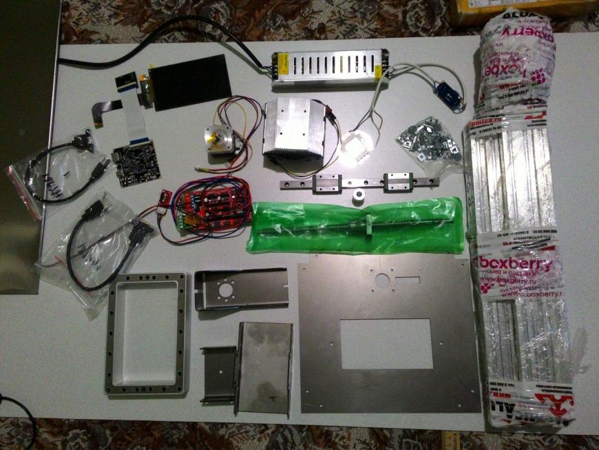
Всем привет! с момента покупки мною китайской прюши прошло уже полтора года, далее она мутировала в огромного H-bot из фанеры и профиля из леруа мерлен, 500x500x700 по габаритам и с областью печати 300х300х280, далее был собран из конструкционного профиля(какой же это кайф по сравнению с профилем из Леруа) небольшой относительно предыдущего H-bot’а дрыгостол по механике напоминающий Up Plus, mz3d, Felix и подобных(который успешно трудится у меня на работе).
И вот пришла пора оторватся от FDM и попробовать что то новое, давно заглядывался на DLP принтеры с проектором, но слишком уж дорого для меня покупать вещь с работой и параметрами которой я мало знаком (излучение, люмены и прочее) да еще что то в ней модифицировать на свой страх и риск, да еще за 40-60 тысяч.
Потом случайно увидел видео как буржуй сделал принтер из экрана от малинки и уф светодиодов и ‘загорелось’, потом нашел у китайцев так называемые DUP (DirectUvPrint) YHD-101 и KLD-LCD 1260 и пока я делал проект, изучал некоторые нюансы искал нужный экран и ждал некоторые запчасти вышел ванхао D7, с него и предыдущих двух братьев я взял примерную конструкцию.
Я расскажу немного если кто-то захочет собрать что-то подобное, чтобы снять часть вопросов, да и в целом показать что технология работает и можно не покупать готовый принтер а сделать всё самому или почти всё если лень 😉 заодно приму участие в конкурсе #самодельныйпринтер
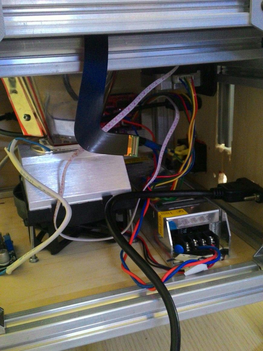
Схема выглядит примерно так:
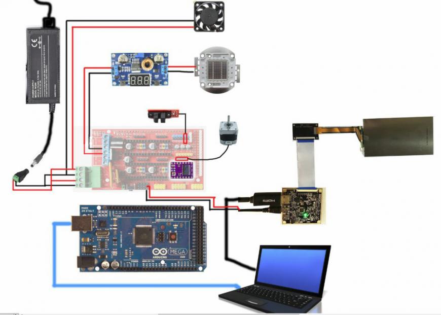
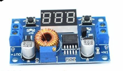
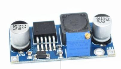
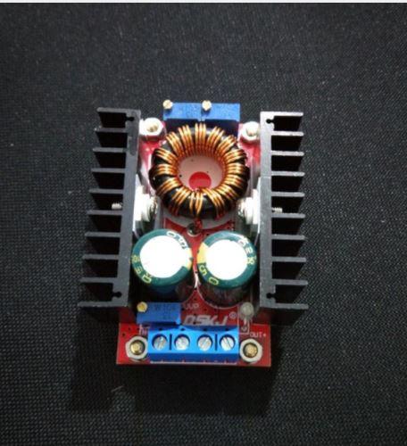
только потом пришлось поставить понижайку с 12 на 5 волт на питание экрана, от серво пинов я не смог его завести и еще нюанс: если ставить диод мощностью больше 10 ватт, то между рампс и диодом надо ставить повышающий преобразователь до 32 вольт.
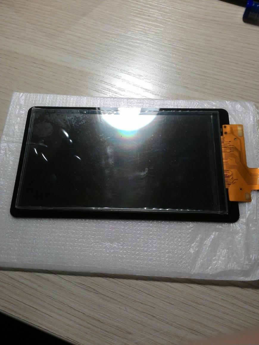
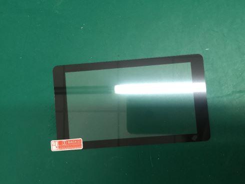
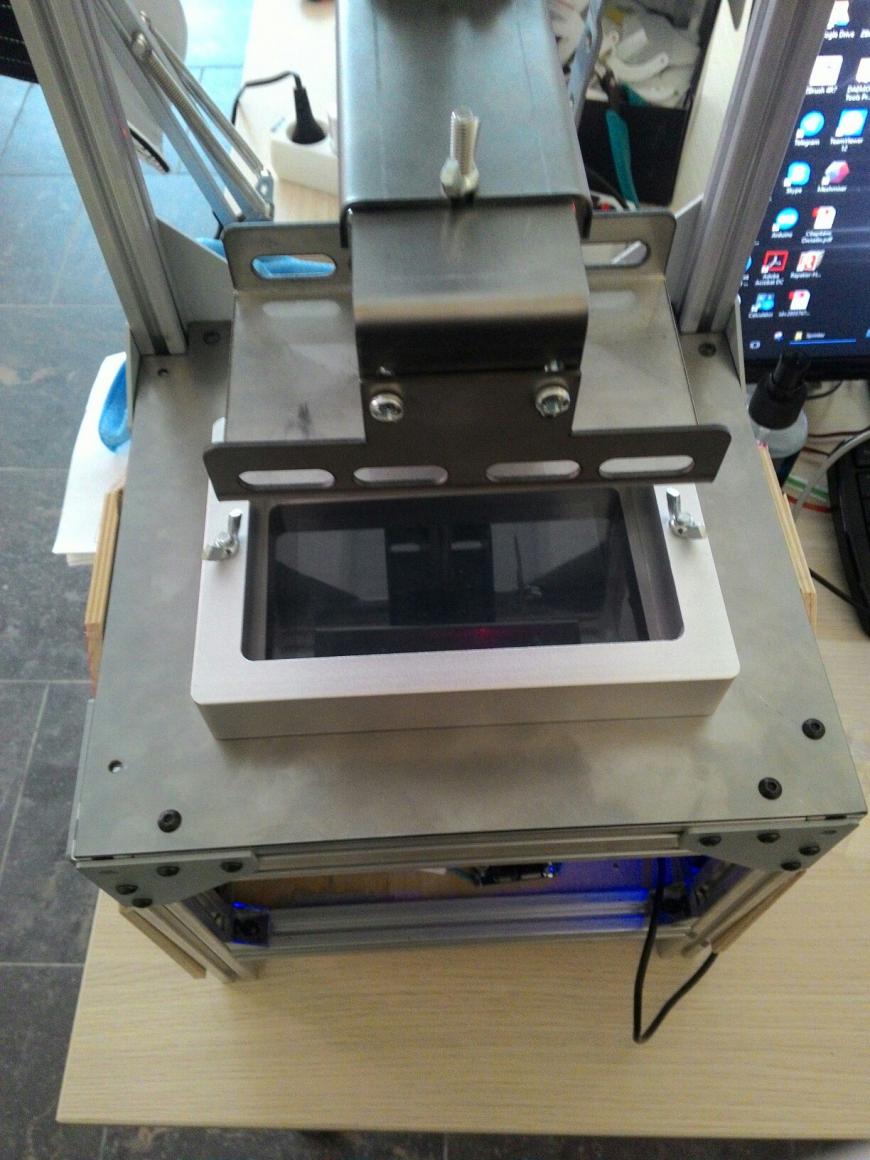
так выглядит экран с контроллером и адаптером:
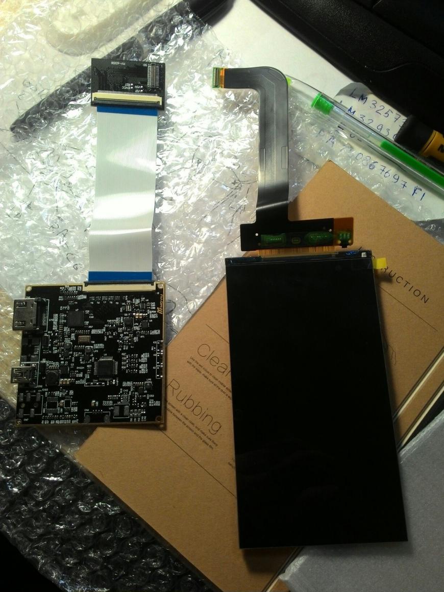
Экран выполняет роль проектора ‘маски’. На нем обтображается срез слоя модели белым цветом на черном фоне, белая область пропускает уф, а черная нет, таки образом формируется нужная картинка которая позволяет затвердеть жидкому полимеру только там где это необходимо.
К сожалению продавцы отказываются продавать такие ‘готовые’ комплекты пока не купишь у них принтер, да есть похожие комплекты, но они не подготовлены для установки в принтер, с них нужно убирать подсветку и защитные пленки, на робофоруме один человек купил такой экран и в итоге он у него хрустнул когда он пытался снять пленку и подсветку (http://roboforum.ru/forum107/topic17271.html)
Увы я не нашел аналогов где не пришлось бы шаманить с удалением задней подсветки, поляризационных пленок и т.д. и после долгих уговоров один продавец согласился продать мне уже готовый комплект, а потом и начал продавать всем желающим, если кто то захочет собрать нечто подобное то вот ссылка:
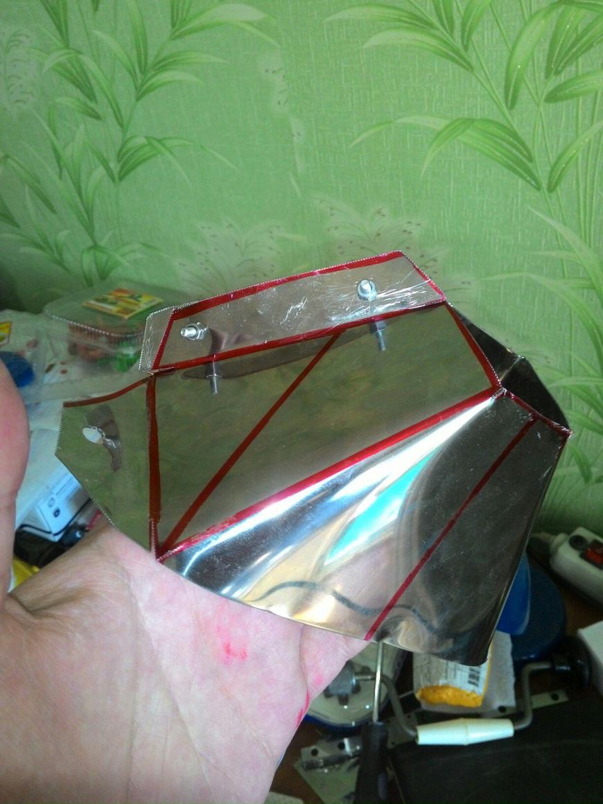
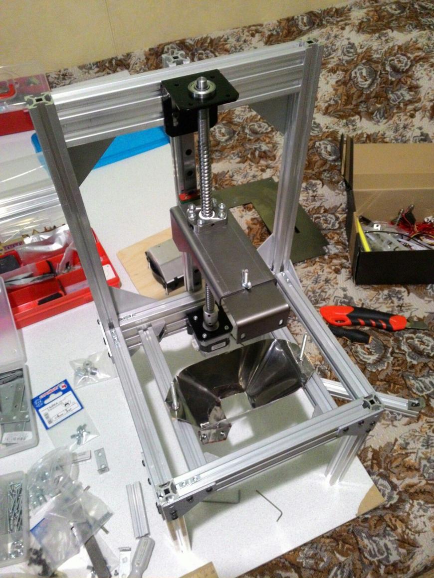
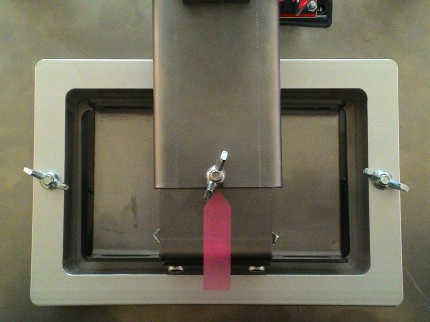
Мне очень не хотелось заморачиваться с ванной для полимера и поэтому я ее просто купил:
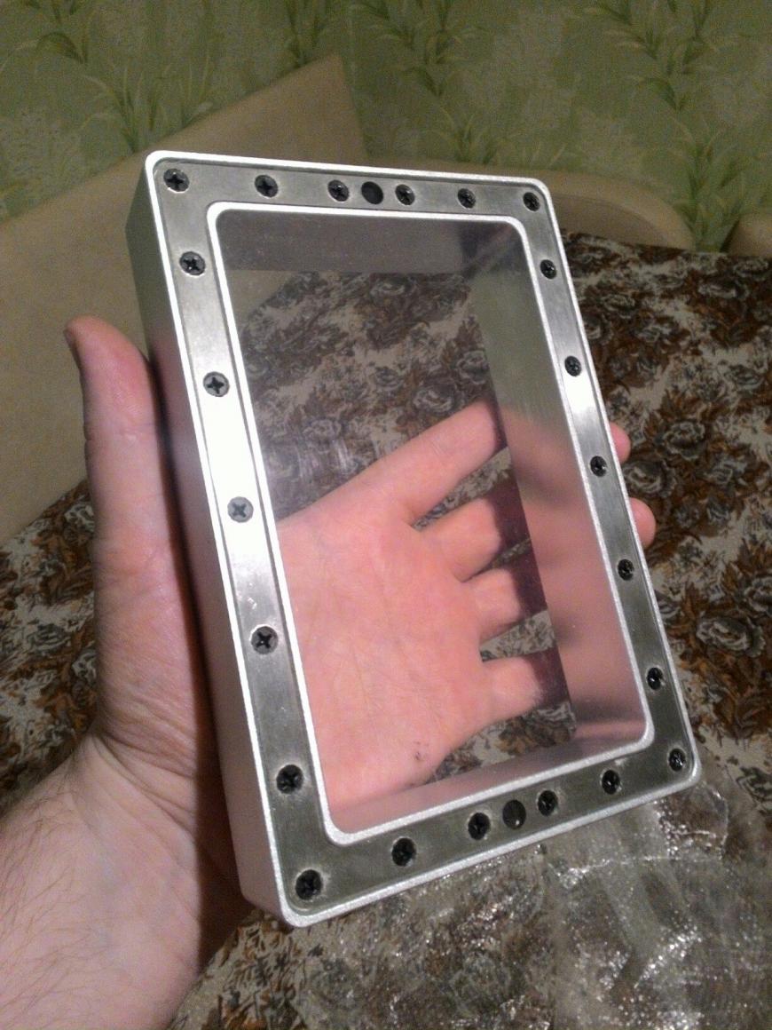
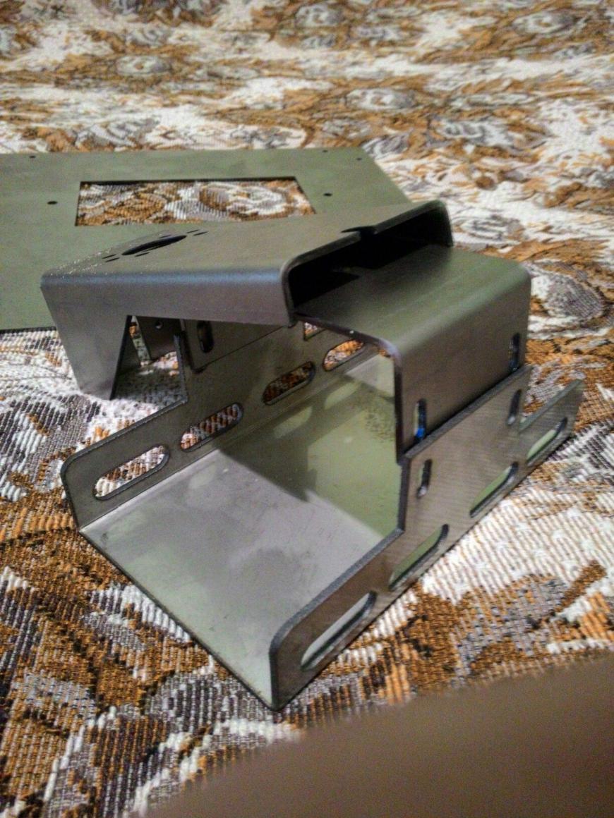
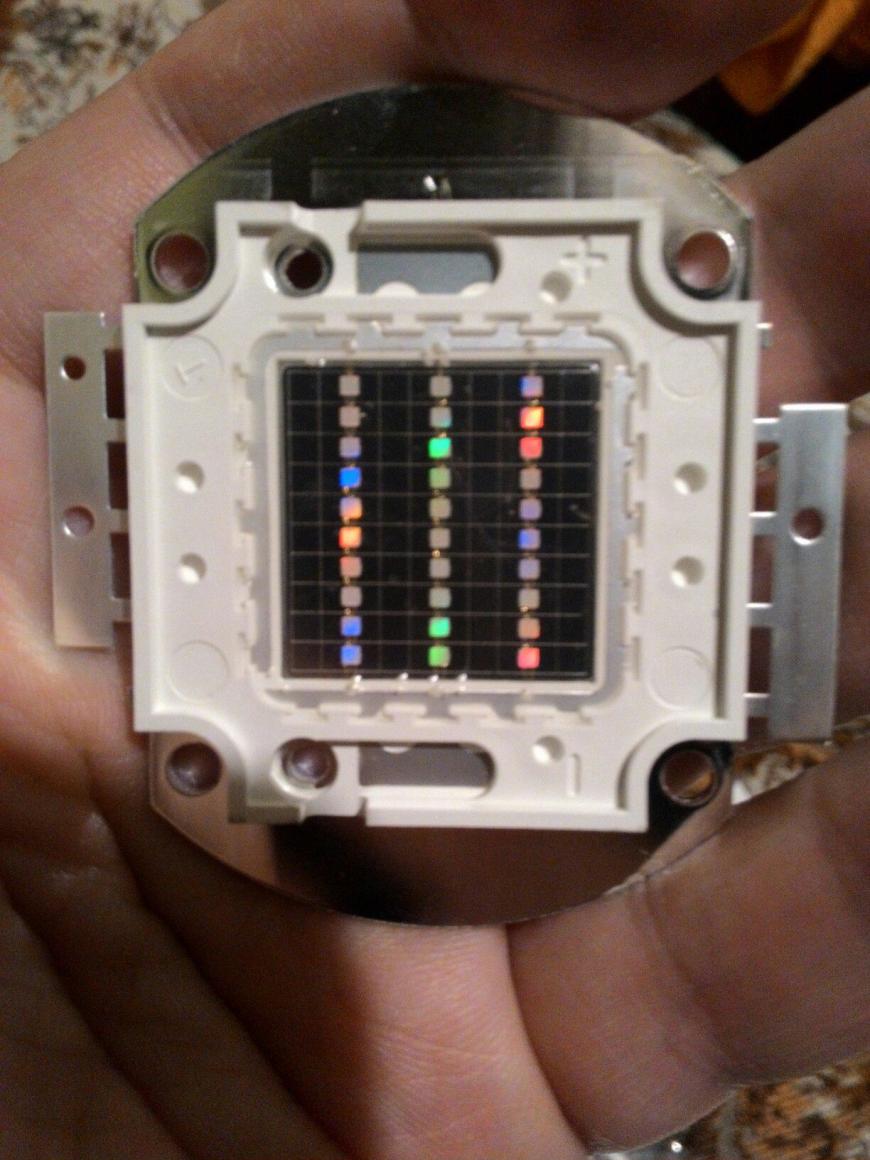
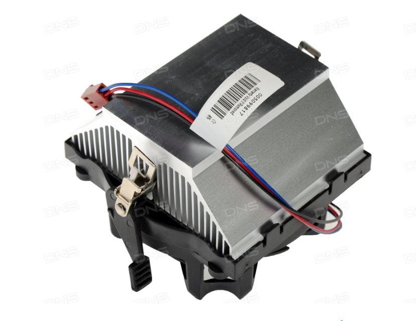
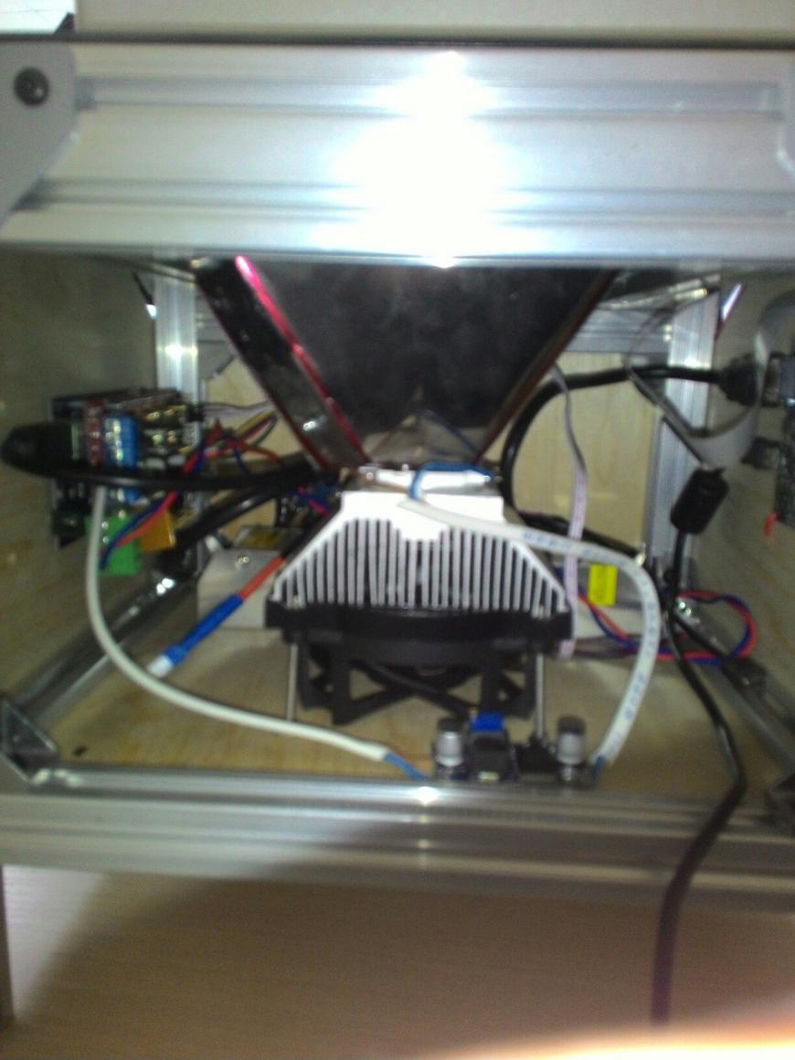
в верхней части сверлятся 4 отверстия и к ним прикручивается светодиод через термопасту, винты м3 как раз плотно заходят между зубьев радиатора.
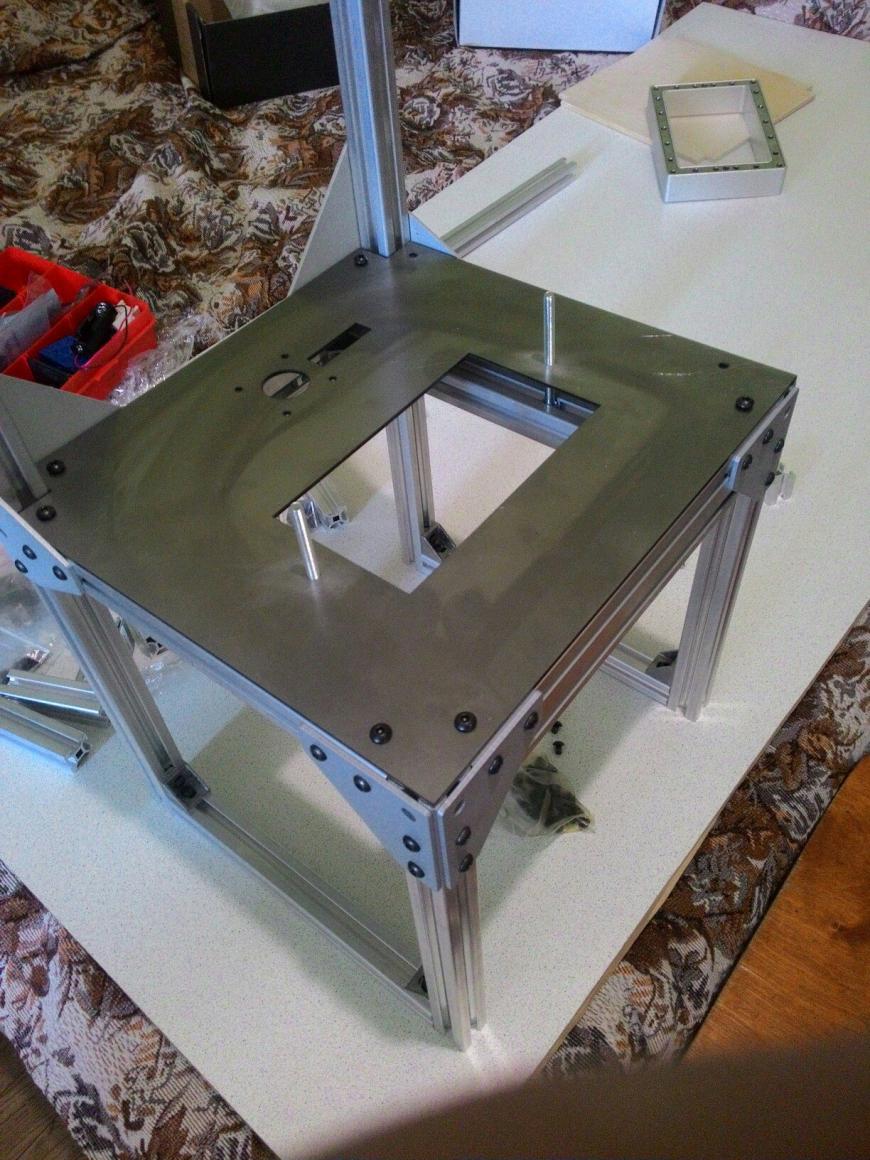
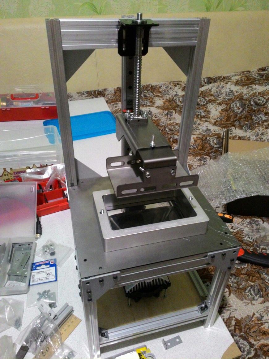
корпус я решил сделать из конструкционного профиля алюмика, (у собери завода с доставкой проблемы) и бока закрыть фанерой:

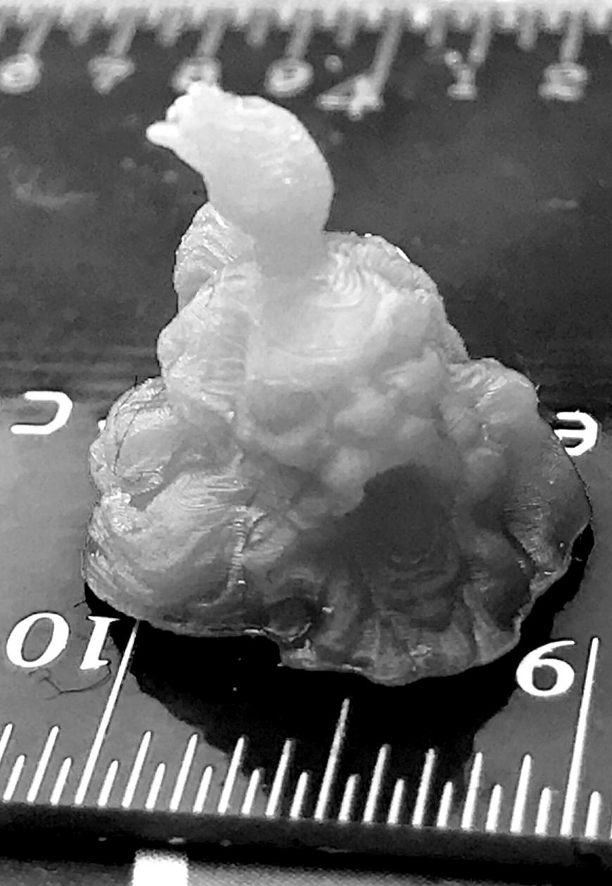
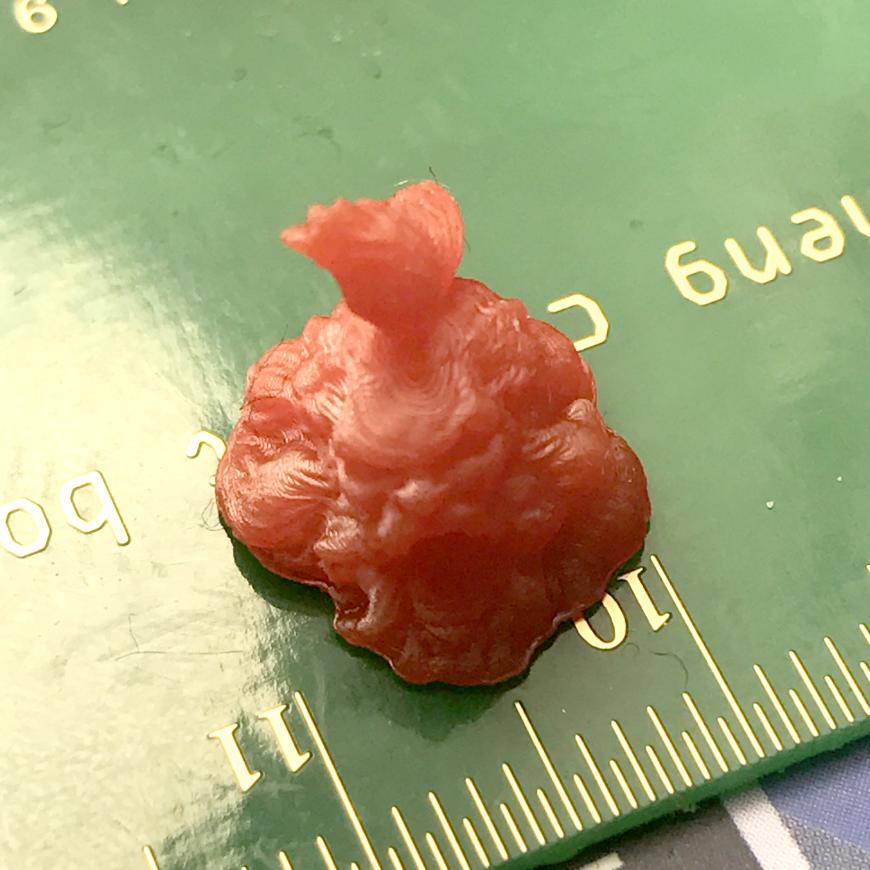
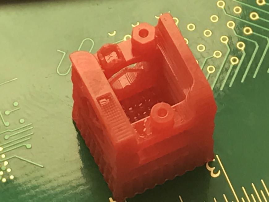
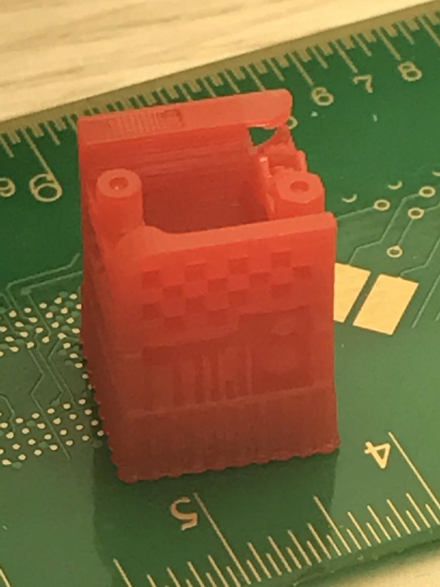
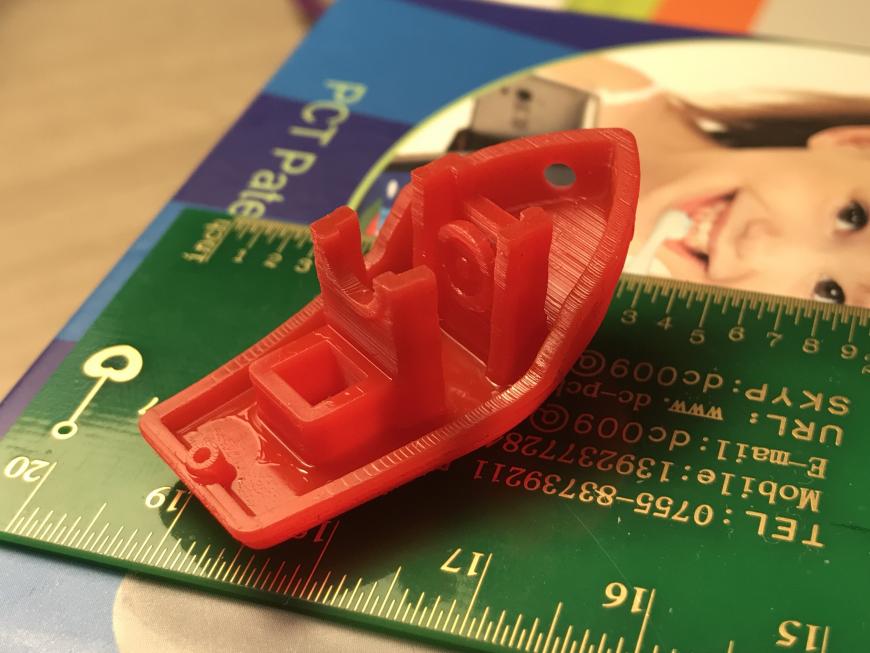
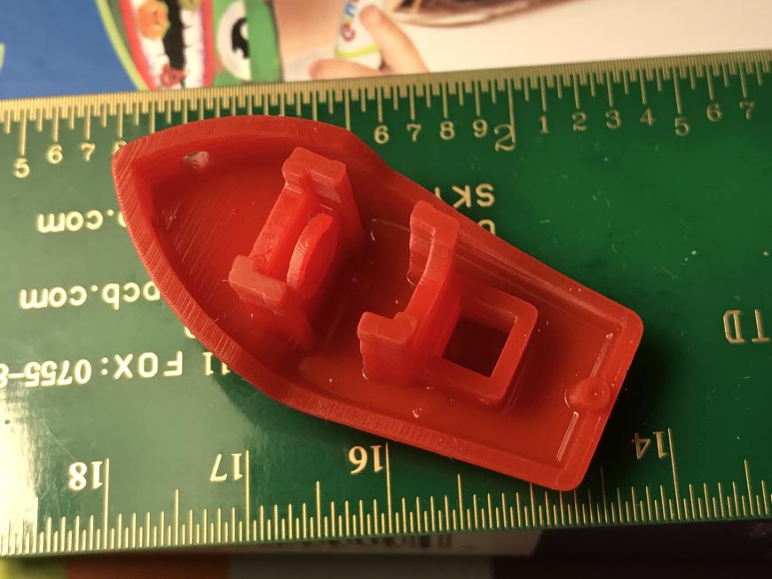
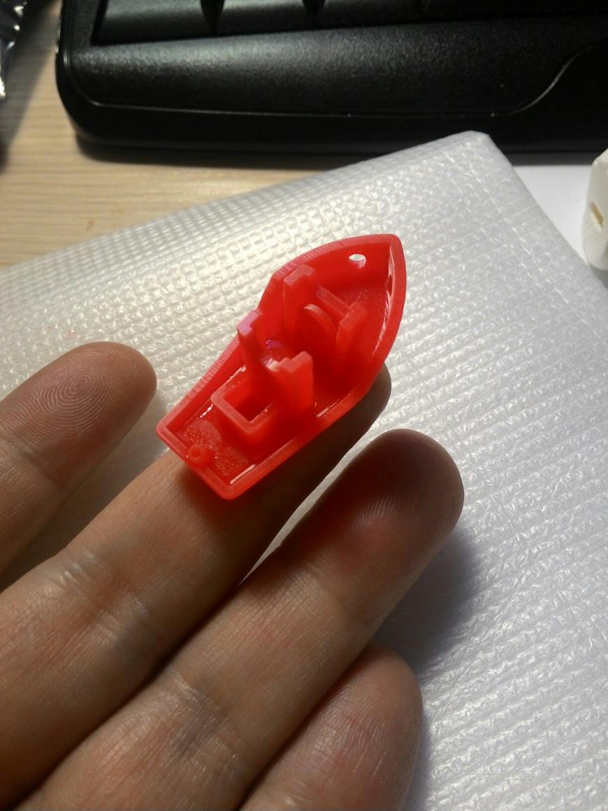
Увы с качеством распечатак пока всё не очень хорошо, толи полимер не очень толи лыжи не едут,;)
мелкие тонкие стенки остаются на пленке, а не на платформе, хотя против этого помогает длительность засветки, в тоже время сполшные детали довольно неохотно отлипают от пленки+ заметил небольшой воблинг, но это уже мой косяк, бюджет начал подползать к готовому принтеру (особенно изза покупки ванночки) но надо было послушать Диму (dagov) и ставить 2 рельсы а не одну.
Заранее извиняюсь за качество фото и постановку света, по другому не умеем8) да и цвет и прозрачность полимера добавляют проблем:
Впереди еще апгрейд, установка второй рельсы, замена пленки ванночки, пробы других полимеров, тесты настроек и т.д.
если есть вопросы или советы пишите в комментариях или в личку
могу так же дать ссылки на детали которые я покупал, ничего не рекламирую и т.д. хотелось лишь поделиться с вами.
Подпишитесь на автора
Подпишитесь на автора, если вам нравятся его публикации. Тогда вы будете получать уведомления о его новых постах.
Отписаться от уведомлений вы всегда сможете в профиле автора.
Источник
Вокруг света с 3Dtoday: SLS-принтер своими руками, 3D-печать в воздухе и другие новости недели!
Подпишитесь на автора
Подпишитесь на автора, если вам нравятся его публикации. Тогда вы будете получать уведомления о его новых постах.
Отписаться от уведомлений вы всегда сможете в профиле автора.
OpenSLS – самодельный лазерный спекающий 3D-принтер
Исследовательская группа биоинженеров из Университета Райса создала SLS-принтер из широкодоступных компонентов. За основу был взят гравер с углекислотным лазером, но большую часть конструкции изобретатели изготовили самостоятельно. По словам разработчиков, себестоимость одного 3D-принтера «OpenSLS» примерно в 40 раз ниже, чем у коммерческих аналогов.


Все наработки команды по созданию бюджетного SLS-принтера выкладываются в открытый доступ по мере совершенствования дизайна. Файлы и инструкции по проекту OpenSLS можно найти здесь.
«Трогательная студия» открывает двери
В Челябинске открывается проект для людей с ограниченными физическими возможностями под названием «Трогательная студия». Задачей студии будет обучение инвалидов работе с программным обеспечением для 3D-моделирования и 3D-принтерами. Своеобразными выпускными работами участников станут напечатанные макеты зданий города, которые планируется передать в городскую библиотеку для слабовидящих и слепых.


Текущий набор завершится 29 февраля, а обучение начнется в марте и будет проходить по субботам. Программа рассчитана на участников, не имеющих каких-либо компьютерных навыков. Организаторы надеются, что полученные знания могут оказаться полезными не только для кругозора, но и выбора профессии и дальнейшего трудоустройства. Дополнительную информацию можно получить здесь.
Эргономика и стиль
Качественные инструменты должны быть не только надежными, но и удобными. Те из нас, кто зарабатывает на жизнь пляской по клавишам, знают цену удобной клавиатуре. И ничто так не напоминает о необходимости заботиться о собственных руках, как кот, перепуганный хрустом разминаемых пальцев! Поверьте на слово.


Создатель не скрывает, что проект весьма сложен, но все же выложил свои наработки в открытый доступ. Файлы для 3D-печати и схемы можно найти здесь, а пока еще простенькое (автор обещает дополнения и уточнения) руководство доступно по этой ссылке.
Не касаясь земли
Корпорация Боинг, имеющая непосредственное отношение к воздухоплаванию, подала заявку на неожиданный, но странным образом вполне профильный патент: метод 3D-печати объектов в подвешенном состоянии.


Выйдет ли что-нибудь из этой затеи или нет, покажет время. Идею же предприимчивые авиастроители уже застолбили, а сам процесс 3D-печати «прямо в воздухе» представляют себе примерно вот так:
Источник
DIY-SLS-3D-Printer

Introduction: DIY-SLS-3D-Printer


In this Instruction, I want to show you how to build a DIY Selektive-Laser-Sintering (SLS) 3D-Printer. I am 17 years old and made everything by myself. Since 6 month my big dream was to build up a working SLS-3D-Printer, but there is a problem. The most SLS-3D-Printers are very expensive and only aviable for the industry. So I build my own printer. Often I was disappointed. Especially with the material, but after a month of experiments I found the right powder for a test print.
Here are some specs:
- 1W 445nm Laserdiode
- 8x8x8cm Buildvolume
- 36x54x60cm Outsidedimensions
- CORE-XY Movement
- Speed: 60mm/s tested, 300mm/s possible
- costs around 400€
### You can find a more advanced second version of the DIY-SLS-3D-Printer here ###
If you like my Instructable, please vote for me in the 3D Printing Contest 🙂
Step 1: Video / Test Prints
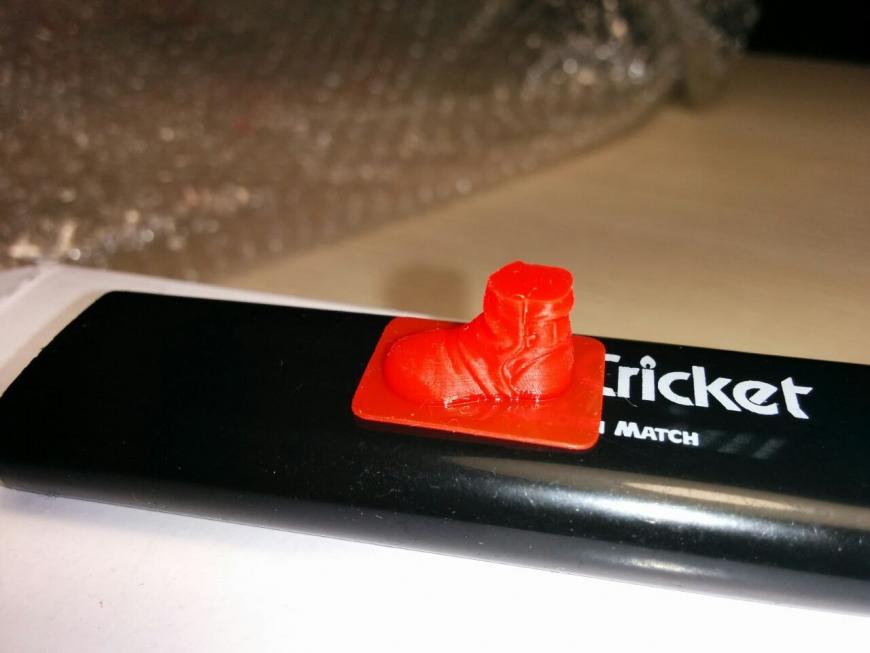
This is my first test print with this printer.
The gear is printed in black powder coating material at 60mm/s.
It has a size of 3x3x0,5cm and took one hour to print.
Video of the gear:
Step 2: CAD-File
(If you can’t see the interactive 3D model above, its probably because you’re not using a WebGL-enabled browser, or you’re using the Instructables Mobile app)
Here you can download the complete CAD-file. .f3d is for Fusion360, .step for other CAD-programms :
Attachments
Step 3: Mechanical-Parts
20x20mm Aluminium-Extrusions:
smooth rods:
- 2x 8x500mm
- 2x 8x285mm
- 2x 8x450mm
- 4x 8x255mm
threaded rods:
bearings:
belts:
Aluminium plates:
I found my plates at the local scrap yard, so I don’t have a link for you.
Screws:
- 8x M4x40mm
- 2x M3x30mm
- 24x M3x8mm
- 8x M3x18mm
- 4x M2x6mm (Endstops)
- 200x M5x10mm DIN912
- 100x M5x10mm ISO7380
Step 4: Electric-Parts
Here are all required electronic parts for the SLS-3D-Printer:
- 1x Arduino Mega 2560 Aliexpress
- 1x Ramps 1.4 Aliexpress
- 4x DRV8825 or 4x A4988 Aliexpress
- 6x Nema 17 Steppermotor Aliexpress
- 1x 445nm 1W TO-18 Laserdiode Ebay
- 1x Laserhousing for TO-18 Laserdiodes Aliexpress
- 3x Microswitch Aliexpress
- 1x Webcam Aliexpress
- 1x Raspberry Pi Pollin
- 1x ATX-Power Supply (from an old PC)
- 2x 120mm fan Aliexpress
Step 5: Printed-Parts
Here is the part list of all required printed parts :
2x powder box.stl
2x Z-Table.stl
2x Z-Motor.stl
2x Z-Axis Top.stl
2x Piston.stl
2x Pusher-Motor.stl
2x Pusher-Idler.stl
2x Pusher.stl
4x 8mm-Rod-holder.stl
2x Motor.stl
1x Idler-Endstop.stl
1x Idler.stl
2x Y-Carriage.stl
1x X-Carriage.stl
1x X-Carriage Top.stl
2x Idler Clamp.stl
2x Belt tensioner.stl
Last change: 10.06.2016
I printed all parts with:
Attachments
Step 6: Build the First Stage
- 2x 500mm Extrusions
- 2x 320mm Extrusions
- 4x M5-Corner Bracket
- 14x M5x10mm DIN912 Screws
- 14x M5 Extrusion Nut
- 8x M5x10mm ISO7380
At first you attach the two Z-Motor printed parts to your base frame. Then you add four M5-Corner brackets to the frame
Step 7: Build the Pistons
- 4x small wood plates
- 3x big wood plates
- 12x wood dowels
I build my pistons out of screen printing plywood, because it is very easy to work with wood. Also it is very cheap :-). An other plus point is that the surface is very smoot, which is better for the piston.
I use some wooden dowels to connect the woodplates to eachother.
I recommend to download my Fusion360 that you can cut the plates very accurate.
Also please look at my additional PDF:
Attachments
Step 8: Connect the Wooden Box to the First Stage
- 4x M5x25mm DIN912 Screws
- 4x M5 hex nut
- 4x M5 washer
Now you can screw the wooden box to the first stage. Use some washers for the M5x25mm screws.
Step 9: Build the Second Stage
- 2x powder box printed part
- 2x Z-Axis Top printed part
- 4x Cornerbracket M5 Nut
- 22x M5x10mm DIN912 Screws
- 22x Extrusion Nut
- 2x 500mm Extrusion
- 2x320mm Extrusion
The main frame of the extrusion is very similar to the frame of the first stage. The only difference between them are the printed parts. For the second stage you need the powder box and the Z-Axis top parts. Connect the parts like in the pictures
Step 10: Pusher
- 1x 300mm Aluminium Extrusion 2020
- 2x Pusher printed part
- 4x LM8UU
- 6x M5x10mm DIN912 screws
- 6x M5 extrusion nut
At first you have to push the 300m Extrusion inside the printed part. Then you connect the extrusion with six M5 extrusion nuts. Before pressing the LM8UU inside the printed part, please predrill the printed part with a 15mm drill.
Step 11: Connect the Second Stage to the Wooden Box/ Install the Pusher Motors
- 2x Nema 17 Motor
- 2x Pusher Motor printed part
- 2x Pusher Idler printed part
- 8x M3x8mm screws
- 12x M5x10mm DIN912 screw
- 2x 608zz Bearing
At first you have to connect the second stage to the wooden box like the firts stage. You simply use four M5x25mm screws. Then you can attach the pusher motor printed part to the second stage. You screw the printed part to the extrusion by using three M5x10mm DIN912 screws. For the Nema 17 motr you use four m3x8mm screws. Once you screwed the motor to the printed part, you attach a 20th GT2 Pulley to the motorshaft. At the other end of the second stage, you attach the pusher Idlers printed parts. Then you push an 608zz Bearing inside the printed parts. This is necessary for the 8mm smooth rod, which will be insert later.
Step 12: Install Z-Axis
- 2x Nema 17 Motor
- 2x Z-table printed part
- 8x M3x8mm screws
- 8x LM8UU
- 2x 8x255mm smoothrod
At first you need to press the LM8UU Bearings inside the Z-Table printed part. Then you simply insert the Z-Table with the LM8UU into the 8mm smooth rods.
Step 13: Pusher
- 2x 8x500mm smoothrods
- 4x 8mm Rod-holder printed part
- 8x M5x10mm DIN912 Screws
- 8x M5 Extrusion Nuts
Now you finished the pusher and the pistion unit for the SLS-3D-Printer. So now you can attach them together. You simply need to push the smooth rods trough the pusher bearings. Then you can screw the smooth rods to the second stage.
Step 14: Y-Carriage
- 2x Y-Carriage
- 4x M4x40mm DIN912 Screws
- 8x F624zz Bearing
- 8x M4 self locking hex nut
- 4x M4 washer
- 4x LM8UU
This is the first step for the X/Y linear Laser movement. The X/Y Movement of this printer based on CORE-XY. If you don’t know what COREXY is, please visit the this website COREXY. The Belt is appropriate on different levels, so the belts don’t rub to eachother. The big advantage of COREXY is, that the weight of the moving mass is lower than conventionell cartesian movement systems. This means that you can drive extremly fast, because you don’t need so much force to accelerate the mass. I’ve tested 400mm/s on my printer 🙂
To build up the Y-Carriage, please take a look at the pictures. Don’t forget to screw the F624zz bearing on different levels. Later this will be very important.
Step 15: Idler
- 2x Idler Clamp printed part
- 1x Idler printed part
- 1x Idler with endstop printed part
- 8x F624zz Bearing
- 4x M4x40mm DIN912 Screw
- 8x M4 self locking hex nut
- 4x M4 washer
Like in the step before. Don’t forget to screw the F624zz bearings on different stages that the belt don’t rub to eachother.
Step 16: X/Y Motor
- 2x Nema 17 Motor
- 1x X-Motor printed part
- 1x Y-Motor printed part
- 8x M3x8mm Screws
- 2x GT2 20th pulley
You need to repeat this step two times. The only difference is, that you use for one the X-Motor-printed part und the other one Y-Motor printed part. Also you have to turn the GT2 pulley of one motor in 180°.
Step 17: Attach the Third Stage
- 2x 8x450mm smoothrods
- 2x 8x285mm smoothrods
- 4x LM8UU
- 12x M5x10mm DIN912 Screws
- 12x M5 Extrusion Nuts
Now you can combine the Y-Carriage, Idler and Motor with the third stage. You push the the smoothrods inside the defined holes. Now you need to screw the X/Y Axis to the third stage. Use the twelve M5x10mm screws to connect the Motr and Idler printed part to the extrusions. Don’t forget to insert four LM8UU for the X-Carriage.
Step 18: Attach the X-Carriage / Last Stage
- 1x X-Carriage printed part
- 4x belt tensioner printed part
- 4x small metal pin
- 8x M3 hex nut
- 2x 2m GT2 Belt
- 8x M3x18mm screws
- 2x 500m Extrusion
- 2x320mm Extrusion
At first you have to install the last stage of extrusions. You simply have to install it like the other extrusions before. After that you can attach the X-carriage to the LM8UU Bearings. You simply have to push them inside the printed part. Then you fix the X-Carriage with four zip-ties. For the Belt you have to put an small metal pin inside the Belt-tensioner. Then you can tighten the belts with the M3x18mm screws. Make sure that your belts have the same lenght!
Step 19: Build the Piston
- 8x M5x25mm screws
- 8x M5 Hex Nut
- 4x Aluminiumplates (12x14cm)
- 8x M3 hex nut
- 2x packing material (From your mechanical parts or etc.)
This step is one of the most important ones, because the pistons are the heart of the printer. I made a lot of experiments, how to make a good piston. So this is my solution 🙂
I am using an aluminium || packing material || aluminium sandwich as a piston. You have to cut the packing material so that it will press itself to the wooden box. The result is that no powder will fall through the piston. You can level the pistons by pressing the aluminium plates together.
Step 20: Install Small Extrusions to the Pusher
To garanteer that all the powder will push inside the next piston, I attached some small 10x10mm Extrusions. Make sure, that the pusher can move freely. The space between pusher and extrusions should be Add Tip Ask Question Comment Download
Step 21: Install the Laser
- 1x Lasermodule
- 4x M3x10mm DIN912 screws
Now can can screw the lasermodule to the X-Carriage. You do that by using four M3x10mm screws. Once you installed the laser, make sure that you are not static charged and touch the lasermodule. The laserdiode is a very sensitive element and can break easily.
Step 22: Outsite Plates
Now you can attach the Aluminium plates for the housing by using some M4x6mm screws. I’am using 1.5mm Aluminium plates for the housing. It is highly recommend to download the Fusion file from the the Top, so you can cut your plates in the exactly dimensions.
Step 23: Powersupply
You can use nearly every ATX-PSU which has a 12v Output. The printer needs all in all less than 100w of power, so you don’t need a strong powersupply, but If you want to change later to an heated piston I recommend not to buy a ATX-PSU. Search on Ebay for server powersupplies. Mostly they are cheaper and have a lot of amps on the 12V Line.
Step 24: Arduino / Ramps 1.4
The Ramps 1.4 is one of the most used electronic boards in the reprap community. It is very cheap and it can be used for many projects. I marked on the picture, where you have to plug your wires that it will work.
Step 25: Laserdriver
If you build your own Laserdriver, I recommend a LM317 constant current circuit. It is cheap and can provide max. 1A for the Laserdiode. You can calculate the current for the laserdiode with this formula: [ I = 1,25 / R1 ]. I’am using an 1,5 Ohm power resistor, so I provide max 0,83 mA for the laserdiode.
I attached a circuit drawing with all the requierd electronic parts (see pictures)
Step 26: Repetierhost
In my opinion Repetier-Host from Repetier the best all in one Software for FDM-3D-Printer. With some modifications you can also use it for my DIY-SLS-3D-Printer.
You don’t have to modify Repetier-Host, beacuse it is just a host software, you have to modify the arduino code and the gCode-generator, that it will work.
Step 27: Arduino-Firmware
To controll the SLS-3D-Printer, I’am using a modifed Repetier-Firmware from Repetier.
This firmware has an feature, that overrides the E-Steps of your Slicer to an Laser, called «Laser-Mode». That means that I can use normal FDM-Slicers like Slic3r for generating the Gcode for my printer.
You can upload the config.h to the Repetier configuration tool . Then download the complete firmware, open it in your Arduino IDE and upload it to your Arduino mega 2560.
Once uploaded, go to Repetierhost—>Config—>Firmware EEprom Configuration.
Then you upload my default Eeprom file, which includes all the parameters like steps per mm, acceleration, feedrate.
You can download my default configurations here:
Attachments
Step 28: Modify Slic3r
I’am using Slic3r to generate the Gcode, because it has some features like custom Gcode on layer change, which is very important for my DIY SLS 3D-Printer, because I need an custom Gcode for the powder pusher.
Slicer is allready included in Repetierhost, so you don’t need to download slic3r as a standalone programm.
You need to open the Slic3r configuration. See pictures, where you have to click
Then you go to —>Printer Settings—> Custom G-code:
Here you type in:
Start G-code
G28 // home all axis
M3 S50 // acctivates the Laser with a power of 50 from 255
End G-Code:
G28 X0 Y0 // home X- and Y-axis
M84 // disable motors
G204 P0 S0 // disable extra Motor for the powder pusher
After Layer change G-code:
G202 P0 X0 // move extra Motor for the powder pusher to 0mm
G201 P0 X300 // move extra Motor for the powder pusher to 300mm
G201 P0 X0 // move extra Motor for the powder pusher to 0mm
( //. = comments, to understand the custom Gcode)
For the other configurations, please download my slicer config file:
Attachments
Step 29: Make Your Print Material
Normaly SLS-3D-Printers printing with Nylon Powder like PA12 which is very expensive. It costs around 200€/kg. This is too expensive for me. If I would fill my buildvolume of 8x8x8cm with PA12. The Material would costs more than my complete printer. So I searched for untypical Materials, which can be sintered, like powder sugar. I mix the powder sugar with some carbon powder, but I had no success. The sugar clumps into small drops (see pictures) und doesn’t create an flat surface.
So I’ve been searching for an other material. Accidentally I found black powder for powder coating on Ebay. It has better characteristics than I expected. I can print the material without a heated bed and with just 200mW laser power at 60mm/s. This is great, but not perfect. The disadvantage of this material is, that it is not very rigid. It breaks easily. But for test prints it is ok.
I think it will work with a material like nylon or an other thermoplast when I add a heated bed, because everything else works nearly perfect (electronics, mechanics, laser. )
If there is someone out there, who has some Ideas about a new material which is inexpensive and can be sintered, please let me know. You would help me a lot.
Step 30: Safety First.
Lasers are very dangerous and can make you blind. Don’t work without safety glasses!


Be the First to Share
Did you make this project? Share it with us!
Recommendations


Rocks, Gems, and Stones Speed Challenge

Micro:bit Contest
Lamps and Lighting Contest

86 Comments

Question 5 months ago on Step 28
Where did you use raspberry pi ?

Question 3 years ago on Step 1
can i use metal powder .

Answer 7 months ago
No, metal powder can oxidise and explode under standard atmosphere, which is why professional machines have a sealed build chambers that are filled with Argon or Nitrogen.

That’s a really nice project ! great ressources so i can start my SLS/ DMLSopen source printer brand. Just a few quick notes though :
— You forgot to mention to ground all metal parts (I assume you still did it) , so just remember to do so
— maybe you could improve printing quality by focusing the laser ? Since you are using an xy carriage instead of a galvo , focusing the laser should be very easy. Also , a focused laser increases its energy density , so by having a very good focus , and a more powerful laser , you could try sintering things like aluminium or maybe copper
— I saw in your other project on sls printers , that you used some form of sugar. Maybe crushing the sugar in a mortar till its very fine could also improve quality.
— I have a few design ideas that would either have a better joint in pistons (you don’t want to get powder all over the place do you ?) or use a powder distributor IN FRONT of the pusher/roller . This way , powder just falls. Also , this makes it easier to refill than a piston , and you don’t have to completely fill it (or offset the piston), you just have to put in the powder you need.
— Is a heated bed necessary ? I think an ir heater from above (just heating the active layer) would be more efficient than heating the powder from under
lastly , maybe you should think about a system for neutral gas injection / fire extinguisher and handler and a sealed system with a vacuum to vacuum the powder BEFORE removing your finished prints (fine powders tend to cause lung issues). Also , a system that would pause the printer if the door is opened during printing ( a 1W laser is considered class 4 , so a little protection wouldn’t be too bad)
Источник