- Создание самодельных аксессуаров для Nintendo Wii
- Предыстория
- Теория
- Реализация
- Yet Another DIY Wii Sensor Bar
- Introduction: Yet Another DIY Wii Sensor Bar
- Attachments
- Step 1: Back and Soldering
- Step 2: Calculate the Distances
- Be the First to Share
- Recommendations
- Rocks, Gems, and Stones Speed Challenge
- Plastic Challenge
- Halloween Contest
- 18 Comments
Создание самодельных аксессуаров для Nintendo Wii
Я являюсь владельцем Nintendo Wii, и недавно мне стало интересно, как же работает «expansion port» на виимоуте, который создан для подключения различных аксессуаров. При этом я не мог не попытаться создать своё собственное устройство для подключения к Wii.
Предыстория
Началось всё с того, что в так называемом «звёздном каталоге» Nintendo я увидел это: 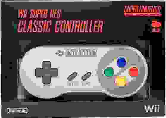
Это контроллер для Wii в виде геймпада от SNES. Для тех, кто не в курсе, расскажу, что на Wii можно официально покупать и играть в игры от NES (у нас больше известна как «Денди»), SNES (aka Super Nintendo), Nintendo 64 и других классических консолей. Чтобы полноценно играть в такие игры, нужно дополнительно покупать «классический контроллер», который представляет из себя обычный геймпад.
Так вот, этот геймпад в виде оригинального контроллера SNES можно «купить» в звёздном каталоге только за звёздочки, получаемые при покупке игр. Проще говоря, его нельзя так просто купить в магазине как обычный классический геймпад, из-за этого эта штука весьма ценится в узких кругах.
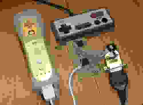
Мне же в голову сразу пришло — почему бы не сделать переходник, который позволял бы подключать к Wiimote (именно к нему подключается классический контроллер, а не напрямую к консоли) настоящий геймпад от SNES, а заодно от NES, Nintendo 64 и чего-нибудь ещё. Так встал вопрос о том, как же устроен порт расширения виимоута.
Теория
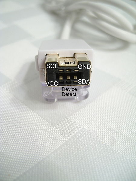
После небольшого гугления выяснилось, что там обычный протокол I²C! В разъёме используется пять контактов: земля, питание, clock, data и определение подключения (туда надо просто подать питание).
Подключаемое устройство должно иметь адрес 0x52. Передаваемые данные зачем-то шифруются. При чём используется 512-битный ключ, который передаёт сам виимоут. Для дешифрации используется простая формула:
Зачем там шифрование? Ума не приложу. К счастью, вскоре выяснилось, что есть уже готовая библиотека для создания своих устройств для Wii:
code.google.com/p/circle-of-current/wiki/WiiExtensionLibrary
Она реализует работу с I²C и шифрование-дешифрование для микроконтроллеров AVR. Как раз то, что мне нужно! Остаётся только подставить ID устройства и заполнить массив передаваемыми данными. Вот ID некоторых устройств:

(Информация с wiibrew.org)
Меня интересовал Classic Controller. Далее нужно было разобраться, в каком формате посылать данные. А передаются там шесть байт:
LX и LY — это левый аналоговый стик (0-63), RX и RY — это правый аналоговый стик (0-31), LT и RT — это аналоговые шифты (0-31), BD
Всё несколько запутанно… Ещё стоит брать во внимание, что при включении происходит калибровка устройства и первое полученное значение с аналогов считается центральным.
Реализация
Таким образом, в спокойном положении геймпада массив из шести байт данных будет выглядеть так:
Старшие биты у стиков равны нулю, всё остальное равно единице. Так будут передаваться данные, в которых стики находятся по центру, и все кнопки отжаты.
Остаётся только изменять эти значения на необходимые и посылать их, когда виимоут опрашивает наше устройство. Первым делом я решил попробовать подключить игровой контроллер от Денди. Т.е. читать нажимаемые на нём кнопки и посылать их в виимоут, имитирую нажатии на классическом контроллере.
Не буду рассказывать о том, как читать данные с геймпада от Денди, эта тема очень избитая, и делается это очень легко. Можете почитать, например, эту статью: habrahabr.ru/post/191936 авторства KurilkaRymin. Впрочем, приведу тут код для этого, он совсем небольшой:
Всё заработало без каких-либо задержек и проблем, если не считать, что дендивские контроллеры время не пощадило, пришлось активно оттирать контакты спиртом. Кстати, как ни странно, им хватает питания в 3.3 вольта, хотя везде пишут, что они питаются от пяти вольт. Я уже морально готовился делать конвертер уровней, но не пришлось.
Теперь я могу играть на Wii в игры от NES на контроллере от Денди. Или на родном контроллере от NES, если достану таковой. Впрочем, они отличаются только наличием читерских кнопок турбо.
В планах:
- Сделать поддержку контроллеров SNES и N64
- Вытравить плату и оформить всё в красивом корпусе
Источник
Yet Another DIY Wii Sensor Bar

Introduction: Yet Another DIY Wii Sensor Bar
I’ve found that the included Wii sensor bar wouldn’t allow me to play games far enough away. This could’ve been due to the actual width limitation of the bar or the strength of the LEDs. Since I use a front projector setup, this required wiring together a solution that allowed the sensor bar to be placed anywhere (and overcome the 10 ft wire extension distance) and also extend the range of the play.
Following the DIY sensor bar initially created by Doctabu, I created one of my own.
My requirements was that I move the Wii around and needed flexibility on the actual play distance. To do that, I wanted two IR LEDs that could be easily repositioned. Thus, a quick trip to the local electronics store yielded me 2 infrared LEDs, 2 battery holders and 2 resistors and 8 AA batteries.
I was aiming for brightness in the IR spectrum and some research had shown that LEDs with a lower 850nm wavelength produced higher degrees of brightness than the higher wavelengths. In the end, my electronics store had a limited selection anyway. The LEDs I was able to obtain were 1.7 forward voltage with a peak current of 50mA. I had a 4 x AA battery pack so that required a 100ohm resistor for each. If you have any other type of LED, your resistor requirement would change. For example, if you choose to use a 2 x AA battery pack for this LED, you’d need a 56 ohm resistor.
Once complete use a digital camera to see the IR light and check that your connections work.
I’ve attached a spreadsheet to calculate the right width that the LEDs need to be spaced apart for any given play distance.
Attachments
Step 1: Back and Soldering
Luckily, there was just enough space to drill a hole and fit the LED and resistor inside. The resistor is important to prevent the LED from burning out.
Step 2: Calculate the Distances
I’ve attached the spreadsheet I used to figure out the exact distance that you need to set the sensors apart for any given play distance.
Setting the LEDs apart by about 17 inches gave me a play distance of 7 to 14 feet which was much more suitable for my front projector setup.
Good luck and hope this was useful.
Be the First to Share
Did you make this project? Share it with us!
Recommendations


Rocks, Gems, and Stones Speed Challenge

Plastic Challenge

Halloween Contest

18 Comments

Your Resistor is too small.
You shouldnt use the peak current for your calculations because they have to lit up constantly. The peak current is only good to use for a short amount of time. It is mostly used to build up some multiplexing circuits where the led only lits up for a short time but frequently. there it is also necessary to use the peak current because when the led only lits up shortly, for the eye it seems that it lits darker than normally so by using the peak current you bring back the brightness. PWM. You know.
But in this setup the led should light permanently and the peak current shortens the lifetime of your led. Yes, you could use a smaller resistor to win some brightness by getting more than the 20mA Normal Forward Current. But I recommend NOT to calculate for the maximum peak current noted in the datasheet. For example: If the normal current is 20mA and the peak is 50mA I would choose 30 or 35mA and calculate for this. So if you want to operate the led under normal conditions it have to be: (6,5V Battery — 1,7V LED) / 0,02A LED = 240 Ohm. For extended brightness: (6,5V Battery — 1,7V LED) / 0,03A LED = 160 Ohm.

There’s a great new kit version of this on Kickstarter http://www.kickstarter.com/projects/1621263610/the-megabar-free-your-wiitm
Seems to be a more complete system. I like their father-son kit idea.

I found a little window burgaler alarm at the dollar tree store. I had the batteries, battery compartment, and a slider switch included for $1. I got rid of the speaker and some the the components on the circuit board. I wired in a 22 ohm resistor, and a VISHAY TSAL 6400 IR LED and a green visible LED (to be a power on indicator). It works great. Either with the Wii console or with Smoothboard.

Is is absolutely necessary to use 4 AAs per LED box? How well would it work with just 1 or 2 AAs?

Reply 14 years ago
For an LED with a 1.7 forward voltage, you need at least 2AAs per LED (with a resistor). You could hook up a single LED but the LED may not light or may stop radiating earlier as the battery wears out.
Reply 14 years ago
oh i forgot to mention that I only used 4AAs because my electronics store only had these handy enclosed battery holders for 4AA and not 2AA. If you go 2AAs, use a 56 ohm resistor
Reply 14 years ago
I made mine, with 2 AAs, but they look really crappy because I just soldered the components and electrical taped them on top. Oh well, not lookin bad for my first ever soldering job :P.
Reply 11 years ago on Introduction
you really should not use the LEDs without a current limiting resistor. You will eventually fry your LEDs. especially since the batteries don’t evenly divide into the voltage.
You are are just going to eat through half the batteries twice as fast. It will be the same thing. You could use 2 LEDs and run them off of 2 1.5 volt batteries (any kind AA AAA, AAAA, C-cells, D-cells anything as long as you get 3 total volts)
If it were me I would use C-sized batteries (and a resistor). they will last for Eons.
also radioshack high output LEDs are 1.28volts not 1.7 volts.

id put another small red led in so you can tell whether is on with out looking at the switch
Reply 11 years ago on Introduction
Actually you probably can’t for two reasons
1) the different voltage/current requirements of the red LED might cause problems. You could wire it up in parallel with it’s own current limiting resistor but that seems like a hassle.
2)it is going to eat up your battery time. I would only do it if you are running it off of a power-supply

the wiimote has an infared cam in it right all you need is two candles place on tv light them up and your wiimote should react to it trust me i tried it

I’m a bit of a novice when it comes to soldering. Did you cut the negative wire completely and just solder the LED to the component on the far left. Also the closest LED I could find with these specs were a pair of emmiters and detectors, which do i use?

Reply 13 years ago on Introduction
Use the emmiters. They emit IR light and the detectors detect the IR light.
I don’t think the angle of the LEDs is so much the issue as the spread. The LEDs radiate enough to get picked up from the side. Use your digital camera to take a look. I think the limiting factor (and probably the reason why the original sensor bar has 2 sets of multiple LEDs) is the distance between the two LEDs as perceived by the wiimote. Given a certain distance from the screen, as you move sideways the angle perceived by the wiimote of the 2 IR points decrease. If I had to redo this project, I would probably probably build into each set more LEDs across so that the width of play is expanded. An easy way is to figure out at what range from the screen you expect to play and then pick the midpoint and calculate your spread required. A bigger spread allows you to play in a wider field but is not effective up close. Up close (which is how Nintendo set its sensor bar spread) can only be achieved by a narrower spread. I can upload a spreadsheet which is my rusty trigonometric attempt at figuring out the actual play area (distance from the screen and effective side play area) given the LED spread. Suffice to say, at 16 inch spread, you get a play area at 7 to 10 feet from the screen that is 6 feet from center either side (12 feet wide). Going past 10 feet and the play area narrows. A apread at 24 inches would make anything less than 9 feet from the screen unplayable (except from the sides) but at 10 feet to 14 feet you’d get a play area that is 8 feet from center either side (16 feet wide). going back fruther from 14 feet and the play area narrows. The setup has been working beautifully for me and am so happy that I did this.
Reply 14 years ago
I used your design, but ended up using 10mm LEDs, 850nm. 2 in a series on each box. Each box holds 4 1.2V AA 15 minute rechargeable batteries, and I used a 22 ohm resistor. So far so good, except that I guess the spread angle is not great on the LEDs I bought. so I pretty much have to be facing directly at them. Basically I have to angle them slightly up to use them standing up, angle them straight when sitting down on the couch, but my range is huge now and accuracy from way back is MUCH better.
This is exactly what I was looking for. My only question is, would it be a good idea to have 2 or 3 LEDs in each box slightly angled apart, or would I get the same results with just one pointing straight forward? Being in a large room, multiple players tend to be further apart and I didn’t know what kind of playing angle the single LED allows. How is this setup working out for you?

Wow, I could’ve swore you used a project box, very nice. i have an idea, a foot pedal switches the normal distance set of LEDs with a group of more farther apart LEDs thus you can step on the pedal and have a instant boost in pinpoint control, basically you make the wiimote think you moved closer to the screen when really you didn’t i never played a wii so i don’t know if that sounded practical
Reply 14 years ago
It was lucky for me that the battery holder was completely enclosed, otherwise it would’ve been a project box. Your foot pedal idea could work but in reverse. moving closer makes the movement of the wiimote more sensitive (ie greater movement for the same angle of wiimote movement). But then, the whole idea of the wii is to move about a bit more so maybe not! 😉
Источник